1.
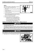
Open the engine side cover at the rear right of the ma-
chine.
2.
Pull out dipstick (G) and wipe the oil off with a cloth.
3.
Fully insert dipstick (G) into the dipstick pipe, then remove
it.
It is appropriate if the oil level is between marks H and L.
If the oil level is below L mark, add oil through oil filler port
(F).
4.
If the oil level is higher than H mark, drain excessive oil
from drain plug (P).
5.
Check the oil level again.
6.
If the oil level is proper, tighten oil filler cap (F) securely.
7.
Close the engine side cover.
REMARK
• When checking the oil level after the engine has been
operated, wait for at least 15 minutes after stopping
the engine before checking.
• If the machine is inclining, make it level before check-
ing.
• When the ambient temperature is low, water or emul-
sified matter may stick to the dipstick, fuel filler cap,
etc. or the drained oil may be milky white because of
water vapor in the blowby gas. However, if the coolant
level is normal, it is not a problem.
• If the coolant level is low, add coolant.
METHOD FOR CHECKING DUST INDICATOR
1.
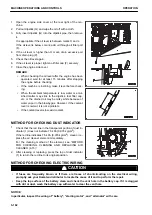
Check that the red line in the transparent portion of dust in-
dicator (1) does not indicate 7.5 kPa {0.076 kg/cm
2
}.
If the red line indicates 7.5 kPa {0.076 kg/cm
2
}, clean or re-
place the air cleaner element immediately.
For the cleaning method of the element, see “METHOD
FOR CHECKING, CLEANING AND REPLACING AIR
CLEANER (4-15)”.
2.
After cleaning or replacing, press the top of dust indicator
(1) to return the red line to its original position.
METHOD FOR CHECKING ELECTRIC WIRING
k
k
CAUTION
• If fuses are frequently blown or if there are traces of short-circuiting on the electrical wiring,
promptly ask your Komatsu distributor to locate the cause of it and to perform the repair.
• Keep the top surface of the battery clean and check the vent hole in the battery cap. If it is clogged
with dirt or dust, wash the battery cap with water to clear the vent hole.
NOTICE
In particular, inspect the wiring of “battery”, “starting motor”, and “alternator” with care.
MACHINE OPERATIONS AND CONTROLS
OPERATION
3-162
Содержание WA480-8
Страница 2: ......
Страница 19: ...Distributor name Address Phone Fax Service personnel FOREWORD PRODUCT INFORMATION 1 17...
Страница 29: ...LOCATION OF SAFETY LABELS SAFETY SAFETY LABELS 2 3...
Страница 69: ...OPERATION Please read and make sure that you understand the SAFETY section before reading this section 3 1...
Страница 76: ...Outside of cab 1 Slow blow fuse 2 Dust indicator 3 Articulation lock pin 4 Toolbox GENERAL VIEW OPERATION 3 8...
Страница 159: ...SWITCHES 1 ECSS switch 2 Front working lamp switch OPERATION EXPLANATION OF COMPONENTS 3 91...
Страница 302: ...Securing position Fixing angle A 61 B 53 C 33 D 38 TRANSPORTATION OPERATION 3 234...
Страница 324: ......
Страница 325: ...MAINTENANCE Please read and make sure that you understand the SAFETY section before reading this section 4 1...
Страница 397: ...Viewed from the rear side of the machine MAINTENANCE MAINTENANCE PROCEDURE 4 73...
Страница 402: ......
Страница 403: ...SPECIFICATIONS 5 1...
Страница 405: ...1 Value when bucket dump angle is 45 B I A G E H F D C 9 J W0 1 4 5 6 SPECIFICATIONS SPECIFICATIONS 5 3...
Страница 406: ......
Страница 422: ......
Страница 423: ...REPLACEMENT PARTS 7 1...
Страница 439: ......
Страница 440: ...WA480 8 WHEEL LOADER Form No VENAM51500 2018 KOMATSU All Rights Reserved Printed in Europe 07 2018...

