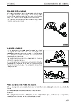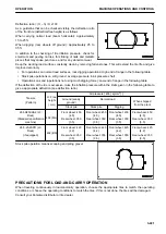
Deflection ratio = (H − h) / H x100
As a guideline that can be checked visibly, the deflection ratio
of the front tire (deflection/free height) is as follows.
When carrying normal load (boom horizontal): Approximately
15 to 25 %
When digging (rear wheels off ground): Approximately 25 to
35 %
In addition to the checking of tire inflation pressure, check for
small cuts and peeling on tires, for sticking of nails and metallic
pieces that may cause punctures, and for any abnormal wear.
Keep the working road surface constantly clean by removing fallen stones. This will extend the tire life and give
improved economy.
• For operations on normal road surfaces, rock digging operations: High end of range in the following table.
• Stock pile operations on soft ground: Average pressure in air pressure chart
• Operations on sand (operations not using much digging force): Low end of range in the following table
If the deflection of the tire is excessive, raise the inflation pressure within the limits given in the following table to
give a appropriate deflection (see deflection ratio).
Tire size
(Pattern)
H: Free
height
( mm)
Air pressure [ kPa { kg/cm
2
} ]
Ground (sandy
ground)
Normal road
When shipped
from the plant
Stock pile
Stock pile
Digging
26.5R25XHA2 (L3:
Rock)
(Standard specification
machine)
492 (ML)
Front wheel: 450
{4.5}
Rear wheel: 350
{3.5}
Front wheel: 450
{4.5}
Rear wheel: 350
{3.5}
Front wheel: 450
{4.5}
Rear wheel: 350
{3.5}
Front wheel: 450
{4.5}
Rear wheel: 350
{3.5}
26.5-25-20PR (L3:
Rock)
(if equipped)
492 (BS)
Front wheel: 420
{4.2}
Rear wheel: 350
{3.5}
Front wheel: 420
{4.2}
Rear wheel: 350
{3.5}
Front wheel: 420
{4.2}
Rear wheel: 350
{3.5}
Front wheel: 420
{4.2}
Rear wheel: 350
{3.5}
Stock pile operation means scooping and piling gravel.
PRECAUTIONS FOR LOAD-AND-CARRY OPERATION
When traveling continuously in load-and-carry operation, choose the appropriate tires to match the operating
conditions, or choose the operating conditions to match the tires. If this is not done, the tires will be damaged.
Consult your Komatsu distributor or tire dealer.
OPERATION
MACHINE OPERATIONS AND CONTROLS
3-221
Содержание WA480-8
Страница 2: ......
Страница 19: ...Distributor name Address Phone Fax Service personnel FOREWORD PRODUCT INFORMATION 1 17...
Страница 29: ...LOCATION OF SAFETY LABELS SAFETY SAFETY LABELS 2 3...
Страница 69: ...OPERATION Please read and make sure that you understand the SAFETY section before reading this section 3 1...
Страница 76: ...Outside of cab 1 Slow blow fuse 2 Dust indicator 3 Articulation lock pin 4 Toolbox GENERAL VIEW OPERATION 3 8...
Страница 159: ...SWITCHES 1 ECSS switch 2 Front working lamp switch OPERATION EXPLANATION OF COMPONENTS 3 91...
Страница 302: ...Securing position Fixing angle A 61 B 53 C 33 D 38 TRANSPORTATION OPERATION 3 234...
Страница 324: ......
Страница 325: ...MAINTENANCE Please read and make sure that you understand the SAFETY section before reading this section 4 1...
Страница 397: ...Viewed from the rear side of the machine MAINTENANCE MAINTENANCE PROCEDURE 4 73...
Страница 402: ......
Страница 403: ...SPECIFICATIONS 5 1...
Страница 405: ...1 Value when bucket dump angle is 45 B I A G E H F D C 9 J W0 1 4 5 6 SPECIFICATIONS SPECIFICATIONS 5 3...
Страница 406: ......
Страница 422: ......
Страница 423: ...REPLACEMENT PARTS 7 1...
Страница 439: ......
Страница 440: ...WA480 8 WHEEL LOADER Form No VENAM51500 2018 KOMATSU All Rights Reserved Printed in Europe 07 2018...


