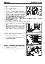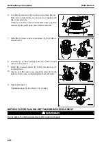
6.
Fit ring (3) to the threaded part of the body and tighten it
with the hand firmly until it stops.
7.
By using the special wrench, further tighten the ring 1/15 to
2/15 turns (1 to 2 ridges of the ring).
If the engine is operated with the ring tightened insufficient-
ly, oil and blowby gas may leak.
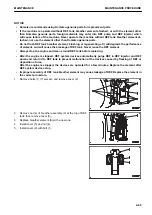
Check the KCCV hose for leakage, crack, and loose clamp, and replace it if necessary.
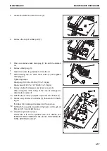
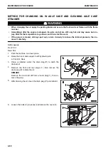
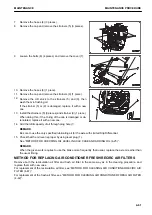
METHOD FOR REPLACING DEF FILTER
k
k
WARNING
Immediately after the engine is stopped, the parts are still very hot. Do not replace the filter immediately.
Wait until all of parts cool down before starting the work.
NOTICE
• Komatsu recommends using Komatsu genuine parts for replacement parts.
• If the machine is operated without DEF filter attached, or with the filter other than Komatsu genuine
parts, foreign materials may enter into DEF pump and DEF injector which will cause failure of the
machine. Never operate the machine without DEF filter attached, nor use the filter other than Komat-
su genuine parts.
• DEF filter cannot be flushed. Flushing or regenerating of it will degrade the performance of filter,
and will cause the breakage of DEF tank. Never reuse the DEF filter.
• Improper assembly of DEF filter may cause leakage of DEF. Replace the DEF filter in the correct pro-
cedure.
• DEF freezes at –11 °C. If it is frozen, replacement of the filter becomes difficult. Replace the filter
when the temperature around DEF pump is higher than -11 °C, and in the condition that DEF is not
frozen.
After the engine is stopped, DEF system devices automatically purge DEF in DEF injector and DEF pump and
return it to DEF tank to prevent malfunction of the devices caused by freezing of DEF or deposition of urea.
After the engine is stopped, the devices are operated for a few minutes. Before replacing the filter, clean around
the DEF pump first after DEF system devices stop.
Items to be prepared
• DEF filter removal tool
• Torque wrench
MAINTENANCE PROCEDURE
MAINTENANCE
4-66
Содержание WA480-8
Страница 2: ......
Страница 19: ...Distributor name Address Phone Fax Service personnel FOREWORD PRODUCT INFORMATION 1 17...
Страница 29: ...LOCATION OF SAFETY LABELS SAFETY SAFETY LABELS 2 3...
Страница 69: ...OPERATION Please read and make sure that you understand the SAFETY section before reading this section 3 1...
Страница 76: ...Outside of cab 1 Slow blow fuse 2 Dust indicator 3 Articulation lock pin 4 Toolbox GENERAL VIEW OPERATION 3 8...
Страница 159: ...SWITCHES 1 ECSS switch 2 Front working lamp switch OPERATION EXPLANATION OF COMPONENTS 3 91...
Страница 302: ...Securing position Fixing angle A 61 B 53 C 33 D 38 TRANSPORTATION OPERATION 3 234...
Страница 324: ......
Страница 325: ...MAINTENANCE Please read and make sure that you understand the SAFETY section before reading this section 4 1...
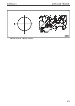
Страница 397: ...Viewed from the rear side of the machine MAINTENANCE MAINTENANCE PROCEDURE 4 73...
Страница 402: ......
Страница 403: ...SPECIFICATIONS 5 1...
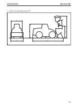
Страница 405: ...1 Value when bucket dump angle is 45 B I A G E H F D C 9 J W0 1 4 5 6 SPECIFICATIONS SPECIFICATIONS 5 3...
Страница 406: ......
Страница 422: ......
Страница 423: ...REPLACEMENT PARTS 7 1...
Страница 439: ......
Страница 440: ...WA480 8 WHEEL LOADER Form No VENAM51500 2018 KOMATSU All Rights Reserved Printed in Europe 07 2018...


