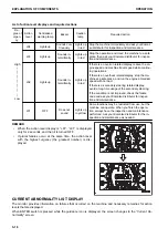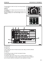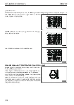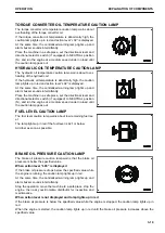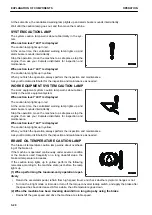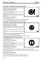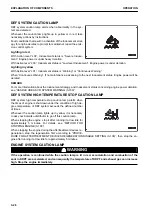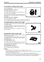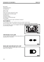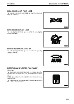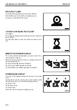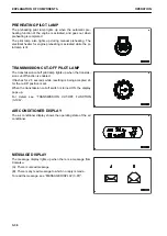
DEF SYSTEM CAUTION LAMP
DEF system caution lamp alerts when abnormality in the sys-
tem are detected.
Whenever the caution lamp lights up in yellow or in red, take
necessary actions by instructions.
Fault conditions that result in activation of the Inducement strat-
egy for engine derates to prompt to maintain or repair the emis-
sion control system.
Lighting in red
With Action level “L04”, Inducement status is “Severe Induce-
ment”. Engine power is under heavy deration.
With Action level “L03”, Inducement status is “Low level Inducement”. Engine power is under deration.
Lighting in yellow
With Action level “L01”, Inducement status is “Warning” or “Continuous Warning”.
When “Continuous Warning”, If no maintenance, advancing to the next Inducement status. Engine power will be
derated.
REMARK
For more information about the Inducement strategy, and Inducement status concerning engine power deration,
see “HANDLE UREA SCR SYSTEM WARNING (3-139)”.
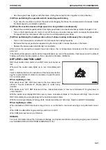
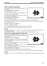
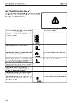
DEF SYSTEM HIGH TEMPERATURE STOP CAUTION LAMP
DEF system high temperature stop caution lamp alerts when
the times of engine is shut down under the condition of high de-
gree temperature of DEF system exceeds the defined number
of times.
Whenever the caution lamp lights up in yellow, it is necessary
to ask your Komatsu distributor to go off this caution lamp.
When stopping the engine, stop it after running it at low idle for
approximately 5 minutes. For details, see “METHOD FOR
STOPPING ENGINE (3-188)”.
When stopping the engine during the aftertreatment devices re-
generation, stop the regeneration first according to “PROCE-
DURE FOR AFTERTREATMENT DEVICES REGENERATION DISABLE SETTING (3-136)”, then stop the en-
gine after running it at low idle for approximately 5 minutes.
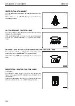
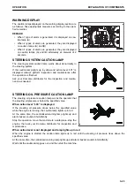
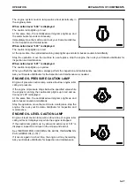
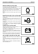
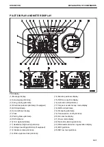
ENGINE SYSTEM CAUTION LAMP
k
k
WARNING
If the operation is continued while the caution lamp is lit in red, accumulation and combustion of the
soot in KDPF are accelerated, and consequently the temperature of KDPF and exhaust gas can increase
high. Stop the engine immediately.
EXPLANATION OF COMPONENTS
OPERATION
3-26
Содержание WA480-8
Страница 2: ......
Страница 19: ...Distributor name Address Phone Fax Service personnel FOREWORD PRODUCT INFORMATION 1 17...
Страница 29: ...LOCATION OF SAFETY LABELS SAFETY SAFETY LABELS 2 3...
Страница 69: ...OPERATION Please read and make sure that you understand the SAFETY section before reading this section 3 1...
Страница 76: ...Outside of cab 1 Slow blow fuse 2 Dust indicator 3 Articulation lock pin 4 Toolbox GENERAL VIEW OPERATION 3 8...
Страница 159: ...SWITCHES 1 ECSS switch 2 Front working lamp switch OPERATION EXPLANATION OF COMPONENTS 3 91...
Страница 302: ...Securing position Fixing angle A 61 B 53 C 33 D 38 TRANSPORTATION OPERATION 3 234...
Страница 324: ......
Страница 325: ...MAINTENANCE Please read and make sure that you understand the SAFETY section before reading this section 4 1...
Страница 397: ...Viewed from the rear side of the machine MAINTENANCE MAINTENANCE PROCEDURE 4 73...
Страница 402: ......
Страница 403: ...SPECIFICATIONS 5 1...
Страница 405: ...1 Value when bucket dump angle is 45 B I A G E H F D C 9 J W0 1 4 5 6 SPECIFICATIONS SPECIFICATIONS 5 3...
Страница 406: ......
Страница 422: ......
Страница 423: ...REPLACEMENT PARTS 7 1...
Страница 439: ......
Страница 440: ...WA480 8 WHEEL LOADER Form No VENAM51500 2018 KOMATSU All Rights Reserved Printed in Europe 07 2018...


