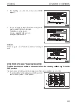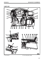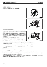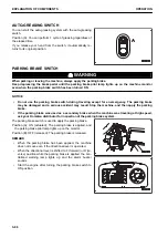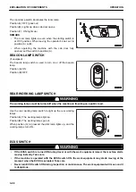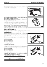
The directional selector enable switch on R.H. switch panel is
used to enable the directional selector switch.
The basic operation is as follows.
Position (A): Directional selector switch is enabled.
Position (B): Directional selector switch is disabled.
When setting the directional selector enable switch on R.H.
switch panel to position (A), set the directional lever and the di-
rectional selector switch to the NEUTRAL position.
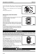
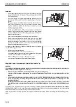
REMOTE POSITIONER SWITCH
The remote positioner switch is used to freely set the stopping position of the boom and bucket.
If you release your hand from the switch, it automatically re-
turns to its original position.
Position (A): Sets or cancels stopping position of boom
Position (B): Sets or cancels stopping position of bucket
For the setting and canceling method of the remote positioner,
see “REMOTE POSITIONER (3-212)”.
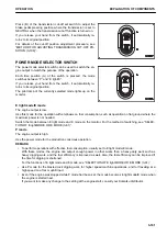
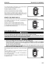
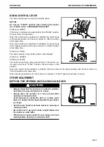
AUTO-DIGGING SWITCH
k
k
WARNING
Keep the auto-digging switch off when other attachments than a bucket are installed.
If you perform the operation without turning off the auto-digging switch, the work equipment may move
unexpectedly, and this may lead to serious personal injury or death.
k
k
CAUTION
• Keep the auto-digging switch off during other works than digging work.
• If the kickdown switch is pressed and the gear is shifted to FORWARD 1st while the auto-digging
switch is set to ON, the mode becomes the auto-digging mode, and the boom may rise automatical-
ly or the bucket may tilt automatically.
• Keep the auto-digging switch off during dozing work. If the auto-digging switch has been set to ON
before the work, the auto-digging may start.
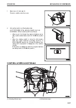
The auto-digging switch is used to turn on and off the auto-dig-
ging.
Each time position (A) of the switch is pressed, the function
switches between ON and OFF.
If you release your hand from the switch, it automatically re-
turns to its original position.
For the method of the auto-digging, see “METHOD FOR AU-
TO-DIGGING (3-203)”.
OPERATION
EXPLANATION OF COMPONENTS
3-103
Содержание WA480-8
Страница 2: ......
Страница 19: ...Distributor name Address Phone Fax Service personnel FOREWORD PRODUCT INFORMATION 1 17...
Страница 29: ...LOCATION OF SAFETY LABELS SAFETY SAFETY LABELS 2 3...
Страница 69: ...OPERATION Please read and make sure that you understand the SAFETY section before reading this section 3 1...
Страница 76: ...Outside of cab 1 Slow blow fuse 2 Dust indicator 3 Articulation lock pin 4 Toolbox GENERAL VIEW OPERATION 3 8...
Страница 159: ...SWITCHES 1 ECSS switch 2 Front working lamp switch OPERATION EXPLANATION OF COMPONENTS 3 91...
Страница 302: ...Securing position Fixing angle A 61 B 53 C 33 D 38 TRANSPORTATION OPERATION 3 234...
Страница 324: ......
Страница 325: ...MAINTENANCE Please read and make sure that you understand the SAFETY section before reading this section 4 1...
Страница 397: ...Viewed from the rear side of the machine MAINTENANCE MAINTENANCE PROCEDURE 4 73...
Страница 402: ......
Страница 403: ...SPECIFICATIONS 5 1...
Страница 405: ...1 Value when bucket dump angle is 45 B I A G E H F D C 9 J W0 1 4 5 6 SPECIFICATIONS SPECIFICATIONS 5 3...
Страница 406: ......
Страница 422: ......
Страница 423: ...REPLACEMENT PARTS 7 1...
Страница 439: ......
Страница 440: ...WA480 8 WHEEL LOADER Form No VENAM51500 2018 KOMATSU All Rights Reserved Printed in Europe 07 2018...

