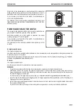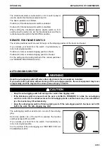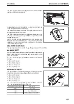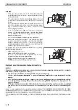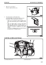
(3) Bucket control lever
(4) Boom control lever
(5) Accelerator pedal
(6) Brake pedal
DIRECTIONAL LEVER
The directional lever switches the machine travel between the
forward and reverse.
The engine does not start if the directional lever is not in NEU-
TRAL position (N).
In such case, the centralized warning lamp lights up and the
alarm buzzer sounds.
Start the engine after turning the directional lever to NEUTRAL
position (N).
Position (F): FORWARD
Position (N): NEUTRAL
Position (R): REVERSE
REMARK
Do not maintain the directional lever at the intermediate position between positions (F) and (N), or between po-
sitions (N) and (R).
Although the transmission operates as displayed on the monitor screen, the alarm buzzer sounds.
STEERING TILT LOCK LEVER
k
k
WARNING
Stop the machine before adjusting the tilt of the steering wheel. If this operation (adjustment) is per-
formed while the machine is moving, serious personal injury or death can result.
The steering tilt lock lever is used to fix the position of the
steering wheel.
(F) FREE position:
The steering wheel is allowed to move back and forth, and up
and down.
(L) LOCK position:
The steering wheel is fixed in the position.
The adjustable range is shown below.
Vertical adjust-
ment
When 0 mm
Top to 40 mm
Tilt adjustment
0 to 129 mm
0 to 162 mm
NOTICE
Do not operate the steering tilt lock lever repeatedly with an excessive force. The lever can be loosened
or its angle can be displaced. In such case, ask your Komatsu distributor for inspection.
EXPLANATION OF COMPONENTS
OPERATION
3-108
Содержание WA480-8
Страница 2: ......
Страница 19: ...Distributor name Address Phone Fax Service personnel FOREWORD PRODUCT INFORMATION 1 17...
Страница 29: ...LOCATION OF SAFETY LABELS SAFETY SAFETY LABELS 2 3...
Страница 69: ...OPERATION Please read and make sure that you understand the SAFETY section before reading this section 3 1...
Страница 76: ...Outside of cab 1 Slow blow fuse 2 Dust indicator 3 Articulation lock pin 4 Toolbox GENERAL VIEW OPERATION 3 8...
Страница 159: ...SWITCHES 1 ECSS switch 2 Front working lamp switch OPERATION EXPLANATION OF COMPONENTS 3 91...
Страница 302: ...Securing position Fixing angle A 61 B 53 C 33 D 38 TRANSPORTATION OPERATION 3 234...
Страница 324: ......
Страница 325: ...MAINTENANCE Please read and make sure that you understand the SAFETY section before reading this section 4 1...
Страница 397: ...Viewed from the rear side of the machine MAINTENANCE MAINTENANCE PROCEDURE 4 73...
Страница 402: ......
Страница 403: ...SPECIFICATIONS 5 1...
Страница 405: ...1 Value when bucket dump angle is 45 B I A G E H F D C 9 J W0 1 4 5 6 SPECIFICATIONS SPECIFICATIONS 5 3...
Страница 406: ......
Страница 422: ......
Страница 423: ...REPLACEMENT PARTS 7 1...
Страница 439: ......
Страница 440: ...WA480 8 WHEEL LOADER Form No VENAM51500 2018 KOMATSU All Rights Reserved Printed in Europe 07 2018...

