METHOD FOR CHECKING AND INFLATING TIRE
k
k
WARNING
• When pumping up the tires, check that no other person is standing near the tire, and install an air
chuck with a clip that can be secured to the air valve.
• To prevent the tire inflation pressure from becoming too high, measure the pressure from time to
time with an air gauge while pumping up the tire.
• When it is inflated, the rim parts may fly out, if they are not fitted properly.
Put a fence around the tire for protection. The worker must not stand in front of the rim but must
stand on the tread side during work.
• Abnormal drop of inflation pressure and abnormal fitting of the rim indicate a trouble in the tire or
rim. In this case, be sure to ask a tire repair shop for repair.
• Be sure to observe the specified inflation pressure.
• Do not adjust the tire inflation pressure immediately after traveling at high speed or operating under
heavy load.
Check the tire inflation pressure before starting work while the tires are cold.
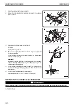
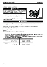
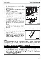
When inflating a tire, use an air chuck which can be fixed to the air valve of the tire as shown in the figure.
Do not work in front of the rim but work on the tread side of the
tire.
1.
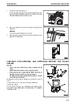
Measure the inflation pressure with a tire inflation pressure gauge.
2.
Adjust the inflation pressure properly.
The proper inflation pressure is shown below.
Tire size
Standard inflation pressure
Standard
26.5R25XHA2
Front wheel: 450 kPa {4.5 kg/cm
2
}
Rear wheel: 350 kPa {3.5 kg/cm
2
}
Optional
26.5-25-20PR
Front wheel: 420 kPa {4.2 kg/cm
2
}
Rear wheel: 350 kPa {3.5 kg/cm
2
}
NOTICE
Appropriate inflation pressure varies depending on the given type of work. For details, see “HAN-
DLE TIRE (3-220)”.
METHOD FOR CLEANING AND REPLACING FUEL BREATHER FILTER
k
k
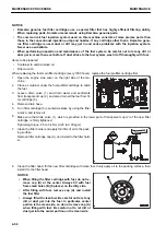
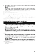
CAUTION
If you inspect or clean while engine is running, dirt enters the fuel tank and damages the engine.
Be sure to stop the engine before performing these works.
MAINTENANCE
MAINTENANCE PROCEDURE
4-37
Содержание WA480-8
Страница 2: ......
Страница 19: ...Distributor name Address Phone Fax Service personnel FOREWORD PRODUCT INFORMATION 1 17...
Страница 29: ...LOCATION OF SAFETY LABELS SAFETY SAFETY LABELS 2 3...
Страница 69: ...OPERATION Please read and make sure that you understand the SAFETY section before reading this section 3 1...
Страница 76: ...Outside of cab 1 Slow blow fuse 2 Dust indicator 3 Articulation lock pin 4 Toolbox GENERAL VIEW OPERATION 3 8...
Страница 159: ...SWITCHES 1 ECSS switch 2 Front working lamp switch OPERATION EXPLANATION OF COMPONENTS 3 91...
Страница 302: ...Securing position Fixing angle A 61 B 53 C 33 D 38 TRANSPORTATION OPERATION 3 234...
Страница 324: ......
Страница 325: ...MAINTENANCE Please read and make sure that you understand the SAFETY section before reading this section 4 1...
Страница 397: ...Viewed from the rear side of the machine MAINTENANCE MAINTENANCE PROCEDURE 4 73...
Страница 402: ......
Страница 403: ...SPECIFICATIONS 5 1...
Страница 405: ...1 Value when bucket dump angle is 45 B I A G E H F D C 9 J W0 1 4 5 6 SPECIFICATIONS SPECIFICATIONS 5 3...
Страница 406: ......
Страница 422: ......
Страница 423: ...REPLACEMENT PARTS 7 1...
Страница 439: ......
Страница 440: ...WA480 8 WHEEL LOADER Form No VENAM51500 2018 KOMATSU All Rights Reserved Printed in Europe 07 2018...


