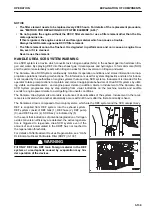
SYSTEM OPERATING LAMP
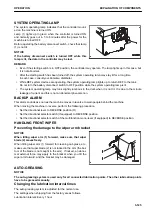
The system operating lamp indicates that the controller mount-
ed on the machine is turned ON.
Lamp (1) lights up in green when the controller is turned ON
and normally goes out in 5 to 6 minutes after the power for the
machine is turned OFF.
Before operating the battery disconnect switch, check that lamp
(1) is not lit.
NOTICE
If the battery disconnect switch is turned OFF while this
lamp is lit, the data in the controller may be lost.
REMARK
• Even if the starting switch is in OFF position, the controller may operate. The lamp lights up in this case, but
it is not abnormal.
• After the starting switch has been turned off, the system operating lamp may stay lit for a long time.
In such case, consult your Komatsu distributor.
• While DEF system devices are operating, the system operating lamp lights up to return DEF to the tank.
Do not turn the battery disconnect switch to OFF position while the system operating lamp is lit.
• The system operating lamp may look slightly luminous in the dark when it is not lit. It is due to the minute
leakage of current and this is not an abnormal phenomenon.
BACKUP ALARM
This alarm sounds as soon as the machine moves in reverse to warn people behind the machine.
When moving the machine in reverse, perform the following procedure.
• Set the directional lever to REVERSE position (R).
• Set the directional selector switch (if equipped) to REVERSE position.
• Set the directional selector switch of the multifunction mono-lever (if equipped) to REVERSE position.
HANDLING FRONT WIPER
Preventing the damage to the wiper arm bracket
NOTICE
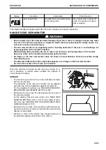
When tilting wiper arm (1) forward, make sure that wiper
blade (2) moves freely.
When tilting wiper arm (1) forward for cleaning cab glass, etc.,
make sure that wiper blade (2) is not locked in the arm (the bot-
tom of the blade is not caught in the arm). If locked, an abnor-
mal external force may apply to the bracket when you tilt the
wiper arm forward, and the bracket may be damaged.
AUTO-GREASING
NOTICE
The auto-greasing system is used only for all connected lubrication points. The other lubrication points
have to be greased manually.
Changing the lubrication interval times
The auto-greasing system is adjusted for the normal use.
The settings when shipping from the factory are as follows.
Lubrication interval: Every 1 hour
OPERATION
EXPLANATION OF COMPONENTS
3-125
Содержание WA480-8
Страница 2: ......
Страница 19: ...Distributor name Address Phone Fax Service personnel FOREWORD PRODUCT INFORMATION 1 17...
Страница 29: ...LOCATION OF SAFETY LABELS SAFETY SAFETY LABELS 2 3...
Страница 69: ...OPERATION Please read and make sure that you understand the SAFETY section before reading this section 3 1...
Страница 76: ...Outside of cab 1 Slow blow fuse 2 Dust indicator 3 Articulation lock pin 4 Toolbox GENERAL VIEW OPERATION 3 8...
Страница 159: ...SWITCHES 1 ECSS switch 2 Front working lamp switch OPERATION EXPLANATION OF COMPONENTS 3 91...
Страница 302: ...Securing position Fixing angle A 61 B 53 C 33 D 38 TRANSPORTATION OPERATION 3 234...
Страница 324: ......
Страница 325: ...MAINTENANCE Please read and make sure that you understand the SAFETY section before reading this section 4 1...
Страница 397: ...Viewed from the rear side of the machine MAINTENANCE MAINTENANCE PROCEDURE 4 73...
Страница 402: ......
Страница 403: ...SPECIFICATIONS 5 1...
Страница 405: ...1 Value when bucket dump angle is 45 B I A G E H F D C 9 J W0 1 4 5 6 SPECIFICATIONS SPECIFICATIONS 5 3...
Страница 406: ......
Страница 422: ......
Страница 423: ...REPLACEMENT PARTS 7 1...
Страница 439: ......
Страница 440: ...WA480 8 WHEEL LOADER Form No VENAM51500 2018 KOMATSU All Rights Reserved Printed in Europe 07 2018...

