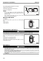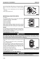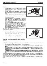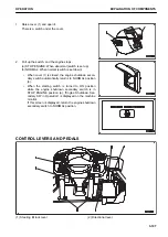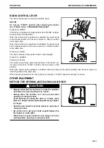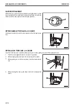
SECONDARY STEERING SWITCH
The secondary steering switch is used to operate the secon-
dary steering manually.
Even when the engine is stopped, pressing this switch allows
operating the steering.
Position (A): ON
The pilot lamp in the switch and the secondary steering pilot
lamp on the machine monitor light up, and you can operate the
steering.
When you release your hand from the switch, it automatically
returns to its original position.
Do not activate the secondary steering except in emergency or checking the function.
The secondary steering is continuously operable up to 60 seconds.
When using the secondary steering, limit the travel speed to 5 km/h or less.
For details, see OPERATION, “HANDLE SECONDARY STEERING SYSTEM (3-199)”.
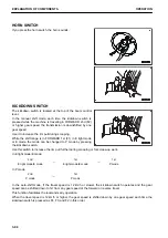
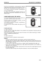
REAR HEATED WIRE GLASS SWITCH
When pressing the switch for rear window glass with heated
wire, the rear heated wire glass is turned ON to clear the glass.
Position (A): ON (Clearing the glass)
Position (B): OFF
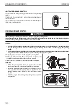
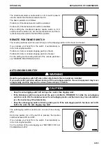
WORK EQUIPMENT LOCK SWITCH
k
k
WARNING
• When leaving the operator's seat, be sure to lock the work equipment by pressing the work equip-
ment lock switch (the pilot lamp lights up). If the work equipment is not locked and the work equip-
ment control lever (A) is touched by mistake, it may lead to serious accident.
• If the work equipment is not securely locked, it can start moving and cause a serious personal in-
jury or death. Check that the pilot lamp is lit.
• Before operating the work equipment lock switch, make sure that work equipment control lever (A)
is in HOLD position.
• When operating the work equipment lock switch, be sure not to touch work equipment control lever
(A).
• Check that your clothes do not get caught by the work equipment control lever (A).
EXPLANATION OF COMPONENTS
OPERATION
3-104
Содержание WA480-8
Страница 2: ......
Страница 19: ...Distributor name Address Phone Fax Service personnel FOREWORD PRODUCT INFORMATION 1 17...
Страница 29: ...LOCATION OF SAFETY LABELS SAFETY SAFETY LABELS 2 3...
Страница 69: ...OPERATION Please read and make sure that you understand the SAFETY section before reading this section 3 1...
Страница 76: ...Outside of cab 1 Slow blow fuse 2 Dust indicator 3 Articulation lock pin 4 Toolbox GENERAL VIEW OPERATION 3 8...
Страница 159: ...SWITCHES 1 ECSS switch 2 Front working lamp switch OPERATION EXPLANATION OF COMPONENTS 3 91...
Страница 302: ...Securing position Fixing angle A 61 B 53 C 33 D 38 TRANSPORTATION OPERATION 3 234...
Страница 324: ......
Страница 325: ...MAINTENANCE Please read and make sure that you understand the SAFETY section before reading this section 4 1...
Страница 397: ...Viewed from the rear side of the machine MAINTENANCE MAINTENANCE PROCEDURE 4 73...
Страница 402: ......
Страница 403: ...SPECIFICATIONS 5 1...
Страница 405: ...1 Value when bucket dump angle is 45 B I A G E H F D C 9 J W0 1 4 5 6 SPECIFICATIONS SPECIFICATIONS 5 3...
Страница 406: ......
Страница 422: ......
Страница 423: ...REPLACEMENT PARTS 7 1...
Страница 439: ......
Страница 440: ...WA480 8 WHEEL LOADER Form No VENAM51500 2018 KOMATSU All Rights Reserved Printed in Europe 07 2018...


