
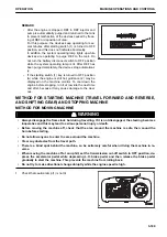


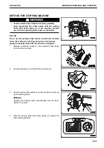

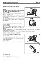


METHOD FOR OPERATING BOOM
The boom control lever is used to control the boom.
NOTICE
Do not use “FLOAT” position when lowering the bucket.
Use “FLOAT” when “LEVELING WORK (3-209)”.
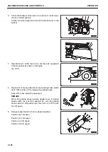
Position (a): RAISE
If the boom control lever is pulled further from “RAISE” position,
the lever stops in that position.
When the remote boom positioner is enabled, the boom stops
at the preset position and the lever returns to “HOLD” position
at the same time.
When the remote boom positioner is disabled, the boom stops
at the highest position and the lever returns to “HOLD” position
at the same time.
Position (b): HOLD
The boom remains in the position where it was stopped.
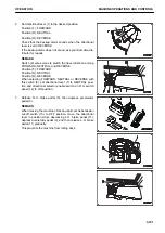
Position (c): LOWER
Position (d): FLOAT
The boom moves freely under external force. If the boom con-
trol lever is turned to “FLOAT” position, the lever stops in that
position.
When the remote boom positioner is enabled, the boom stops at the preset position and the lever returns to
“HOLD” position at the same time.
When the remote positioner is not set, the lever remains in “FLOAT” position and does not return.
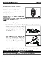
METHOD FOR OPERATING BUCKET
The bucket control lever is used to operate the bucket.
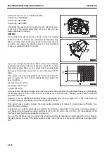
Position (a): TILT
When the bucket control lever is pulled further from TILT posi-
tion, the lever stops in that position. As soon as the bucket
reaches the preset position by the bucket positioner, the lever
returns to HOLD position.
Position (b): HOLD
The bucket remains in the position where it was stopped.
Position (c): DUMP
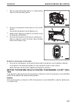
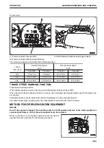
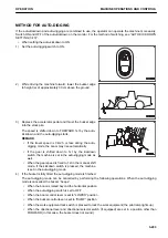
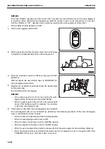
AUTO-DIGGING
The auto-digging system controls the tilting operation of the bucket automatically to facilitate bucket operation
and reduces the fatigue of the operator.
When operating, see “DIGGING WORK (3-207)”.
MACHINE OPERATIONS AND CONTROLS
OPERATION
3-202
Содержание WA480-8
Страница 2: ......
Страница 19: ...Distributor name Address Phone Fax Service personnel FOREWORD PRODUCT INFORMATION 1 17...
Страница 29: ...LOCATION OF SAFETY LABELS SAFETY SAFETY LABELS 2 3...
Страница 69: ...OPERATION Please read and make sure that you understand the SAFETY section before reading this section 3 1...
Страница 76: ...Outside of cab 1 Slow blow fuse 2 Dust indicator 3 Articulation lock pin 4 Toolbox GENERAL VIEW OPERATION 3 8...
Страница 159: ...SWITCHES 1 ECSS switch 2 Front working lamp switch OPERATION EXPLANATION OF COMPONENTS 3 91...
Страница 302: ...Securing position Fixing angle A 61 B 53 C 33 D 38 TRANSPORTATION OPERATION 3 234...
Страница 324: ......
Страница 325: ...MAINTENANCE Please read and make sure that you understand the SAFETY section before reading this section 4 1...
Страница 397: ...Viewed from the rear side of the machine MAINTENANCE MAINTENANCE PROCEDURE 4 73...
Страница 402: ......
Страница 403: ...SPECIFICATIONS 5 1...
Страница 405: ...1 Value when bucket dump angle is 45 B I A G E H F D C 9 J W0 1 4 5 6 SPECIFICATIONS SPECIFICATIONS 5 3...
Страница 406: ......
Страница 422: ......
Страница 423: ...REPLACEMENT PARTS 7 1...
Страница 439: ......
Страница 440: ...WA480 8 WHEEL LOADER Form No VENAM51500 2018 KOMATSU All Rights Reserved Printed in Europe 07 2018...


