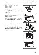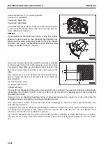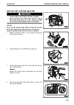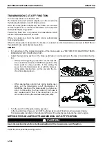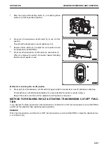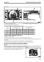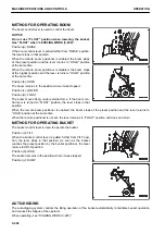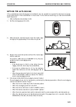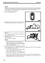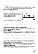
REMARK
• If the gear speed switch is operated slowly or is stopped
between gear positions, the centralized warning lamp may
light up and the alarm buzzer may sound. This is not a fail-
ure in this case.
Operate the gear speed switch so that gear shifting is
completed in 2 seconds.
• This machine is equipped with kickdown switch (2). When
traveling in 2nd, if kickdown switch (2) is pressed, the gear
is shifted down to 1st.
Use of the kickdown switch is recommended for the opera-
tions such as digging and loading that are performed at 1st
and 2nd.
For the operating procedure, see “KICKDOWN SWITCH
(3-94)”.
• This machine is equipped with the auto-shift system for the
automatic gear shifting. For the operating procedure, see
“TRANSMISSION SHIFT MODE SELECTOR SWITCH
(3-102)” and “AUTOMATIC SHIFT (3-105)”.
• When the machine is traveling at high speed, if the gear
speed switch is operated to a slower gear speed such as
from 4th to 3rd and from 4th to 2nd while depressing the
accelerator pedal, the shift down is not enabled to protect
overrun of the engine.
In such case, the centralized warning lamp lights up and
the alarm buzzer sounds.
If the alarm buzzer sounds, release the accelerator pedal
immediately, depress the brake pedal to reduce the speed
and then shift the gear.
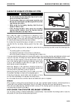
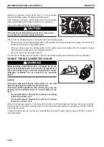
METHOD FOR SWITCHING BETWEEN FORWARD AND REVERSE
k
k
WARNING
• When switching the travel direction between FORWARD and REVERSE, check the safety in new di-
rection in which the machine moves. The area behind the machine is a blind spot.
Particularly pay attention when traveling in reverse.
• Do not make directional change while the machine is traveling at a high speed.
When switching the direction, depress the brake pedal to reduce the travel speed sufficiently, then
switch the direction. (Max. 12 km/h)
• When driving the machine downhill through inertia, set the directional lever to the position that
matches the machine traveling direction. If the direction lever is set to the direction opposite to that
of the machine travel, engine stall can result and it is very dangerous.
You can switch the travel direction without stopping the machine .
OPERATION
MACHINE OPERATIONS AND CONTROLS
3-193
Содержание WA480-8
Страница 2: ......
Страница 19: ...Distributor name Address Phone Fax Service personnel FOREWORD PRODUCT INFORMATION 1 17...
Страница 29: ...LOCATION OF SAFETY LABELS SAFETY SAFETY LABELS 2 3...
Страница 69: ...OPERATION Please read and make sure that you understand the SAFETY section before reading this section 3 1...
Страница 76: ...Outside of cab 1 Slow blow fuse 2 Dust indicator 3 Articulation lock pin 4 Toolbox GENERAL VIEW OPERATION 3 8...
Страница 159: ...SWITCHES 1 ECSS switch 2 Front working lamp switch OPERATION EXPLANATION OF COMPONENTS 3 91...
Страница 302: ...Securing position Fixing angle A 61 B 53 C 33 D 38 TRANSPORTATION OPERATION 3 234...
Страница 324: ......
Страница 325: ...MAINTENANCE Please read and make sure that you understand the SAFETY section before reading this section 4 1...
Страница 397: ...Viewed from the rear side of the machine MAINTENANCE MAINTENANCE PROCEDURE 4 73...
Страница 402: ......
Страница 403: ...SPECIFICATIONS 5 1...
Страница 405: ...1 Value when bucket dump angle is 45 B I A G E H F D C 9 J W0 1 4 5 6 SPECIFICATIONS SPECIFICATIONS 5 3...
Страница 406: ......
Страница 422: ......
Страница 423: ...REPLACEMENT PARTS 7 1...
Страница 439: ......
Страница 440: ...WA480 8 WHEEL LOADER Form No VENAM51500 2018 KOMATSU All Rights Reserved Printed in Europe 07 2018...

