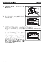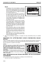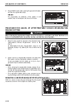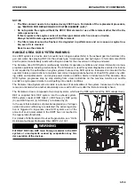
Lubrication time: 12 minutes
When changing the settings of the lubrication cycle for the heavy-duty operations, consult your Komatsu distrib-
utor.
Method for operating the auto-greasing system
The pump with grease tank is located at the position as shown
in the figure.
For details, see “AUTO-GREASING PILOT LAMP”, “AUTO-
GREASING SWITCH”, and “CHECKING AUTO-GREASING
AND OPERATION METHOD FOR FILLING GREASE”.
Turn the starting switch to ON position (B).
The power supply to the grease pump is turned on.
The auto-greasing pilot lamp is lit for 2 seconds.
Display and control unit
The display and control unit are protected by a transparent
plastic cover against sprayed water and mechanical damages.
For setting, the cover needs to be removed and remounted af-
terwards.
LED display
(1) Three-digit LED display: Values and operating state
(2) Pause time
(3) Pump operation
(4) Monitoring of system function by means of an external cycle
switch
(5) Without function
(6) Fault message
EXPLANATION OF COMPONENTS
OPERATION
3-126
Содержание WA480-8
Страница 2: ......
Страница 19: ...Distributor name Address Phone Fax Service personnel FOREWORD PRODUCT INFORMATION 1 17...
Страница 29: ...LOCATION OF SAFETY LABELS SAFETY SAFETY LABELS 2 3...
Страница 69: ...OPERATION Please read and make sure that you understand the SAFETY section before reading this section 3 1...
Страница 76: ...Outside of cab 1 Slow blow fuse 2 Dust indicator 3 Articulation lock pin 4 Toolbox GENERAL VIEW OPERATION 3 8...
Страница 159: ...SWITCHES 1 ECSS switch 2 Front working lamp switch OPERATION EXPLANATION OF COMPONENTS 3 91...
Страница 302: ...Securing position Fixing angle A 61 B 53 C 33 D 38 TRANSPORTATION OPERATION 3 234...
Страница 324: ......
Страница 325: ...MAINTENANCE Please read and make sure that you understand the SAFETY section before reading this section 4 1...
Страница 397: ...Viewed from the rear side of the machine MAINTENANCE MAINTENANCE PROCEDURE 4 73...
Страница 402: ......
Страница 403: ...SPECIFICATIONS 5 1...
Страница 405: ...1 Value when bucket dump angle is 45 B I A G E H F D C 9 J W0 1 4 5 6 SPECIFICATIONS SPECIFICATIONS 5 3...
Страница 406: ......
Страница 422: ......
Страница 423: ...REPLACEMENT PARTS 7 1...
Страница 439: ......
Страница 440: ...WA480 8 WHEEL LOADER Form No VENAM51500 2018 KOMATSU All Rights Reserved Printed in Europe 07 2018...

