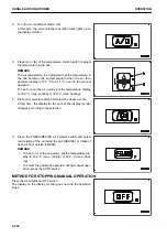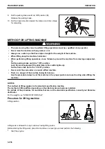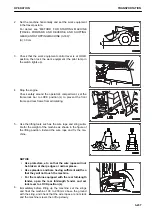
9.
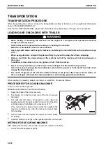
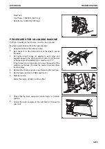
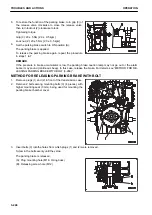
Set the parking brake switch to OFF position (B).
Release the parking brake.
10. Set the travel direction toward the ramps and drive slowly
for unloading.
METHOD FOR LIFTING MACHINE
k
k
WARNING
• The person using the crane to perform lifting operations must be a qualified crane operator.
• Never raise the machine with any worker on it.
• Always use a wire rope that has ample strength for the weight of the machine.
• When lifting, keep the machine horizontal.
• When performing lifting operations, do as follows to prevent the machine from moving unexpected-
ly.
Set the parking brake switch to “ON” position.
Lock the work equipment (the pilot lamp in the switch lights up).
Set the frame lock bar to the “LOCK” position.
• Never enter the area under or around a lifted machine.
• There is a danger of the machine losing its balance.
Use the procedure below to set the machine in the proper posture and use the sling when lifting the
machine.
NOTICE
This method of lifting applies to the standard specification machine.
The method of lifting differs depending on the attachments and options installed.
For details of the procedure for machines that are not the standard specification, consult your Komatsu
distributor.
For the weight, see “SPECIFICATIONS (5-2)”.
Procedure for lifting machine
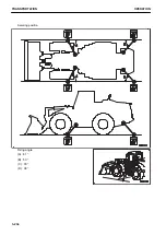
Lifting position
Lifting work is allowed for only machines having lifting marks.
Before starting the lifting work, place the machine on a level ground and perform the following.
1.
Start the engine.
TRANSPORTATION
OPERATION
3-236
Содержание WA480-8
Страница 2: ......
Страница 19: ...Distributor name Address Phone Fax Service personnel FOREWORD PRODUCT INFORMATION 1 17...
Страница 29: ...LOCATION OF SAFETY LABELS SAFETY SAFETY LABELS 2 3...
Страница 69: ...OPERATION Please read and make sure that you understand the SAFETY section before reading this section 3 1...
Страница 76: ...Outside of cab 1 Slow blow fuse 2 Dust indicator 3 Articulation lock pin 4 Toolbox GENERAL VIEW OPERATION 3 8...
Страница 159: ...SWITCHES 1 ECSS switch 2 Front working lamp switch OPERATION EXPLANATION OF COMPONENTS 3 91...
Страница 302: ...Securing position Fixing angle A 61 B 53 C 33 D 38 TRANSPORTATION OPERATION 3 234...
Страница 324: ......
Страница 325: ...MAINTENANCE Please read and make sure that you understand the SAFETY section before reading this section 4 1...
Страница 397: ...Viewed from the rear side of the machine MAINTENANCE MAINTENANCE PROCEDURE 4 73...
Страница 402: ......
Страница 403: ...SPECIFICATIONS 5 1...
Страница 405: ...1 Value when bucket dump angle is 45 B I A G E H F D C 9 J W0 1 4 5 6 SPECIFICATIONS SPECIFICATIONS 5 3...
Страница 406: ......
Страница 422: ......
Страница 423: ...REPLACEMENT PARTS 7 1...
Страница 439: ......
Страница 440: ...WA480 8 WHEEL LOADER Form No VENAM51500 2018 KOMATSU All Rights Reserved Printed in Europe 07 2018...


