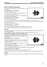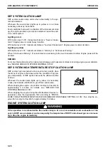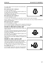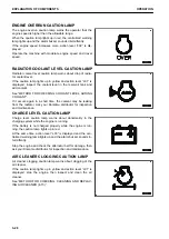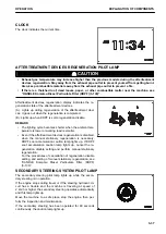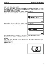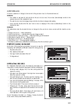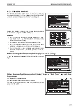
ECO GUIDANCE
ECO guidance is displayed during the operation that lowers the fuel efficiency, and support energy saving oper-
ation for reducing the fuel consumption.
The details of the guidance are as follows.
REMARK
Display/Non-display of ECO guidance can be switched.
For the method of switching the display, see “SWITCH DISPLAY/NON-DISPLAY OF ECO GUIDANCE (3-59)”.
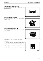
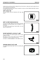
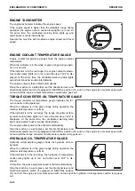
EXCESSIVE IDLING GUIDANCE
If the engine continues running idle for more than 5 minutes,
the excessive idling message is displayed on the monitor.
When waiting for work or taking short break, stop the engine to
reduce unnecessary fuel consumption.
When the accelerator pedal is depressed or the machine starts
traveling or the work equipment is operated, the excessive
idling message goes out.
For the auto idle stop function, see “AUTO IDLE STOP TIMER
SETTING (3-71)”.
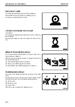
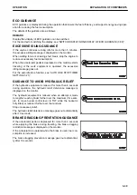
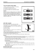
GUIDANCE TO AVOID HYDRAULIC RELIEF
If the hydraulic equipment is relieved for more than 8 seconds
during operation, the hydraulic relief deterrence message is
displayed on the monitor.
The hydraulic equipment is relieved when an attempt is made
to lengthen each cylinder further over the maximum (for exam-
ple, to move bucket control lever to TILT while the bucket is
fully tilted) or reduce it further over the minimum.
Stop unnecessary relief.
The hydraulic relief deterrence message goes out automatically
after 10 seconds.
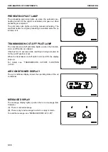
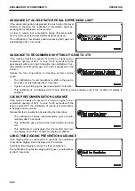
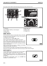
BRAKE DRAGGING PREVENTION GUIDANCE
If the accelerator pedal is depressed for more than 3 seconds
while applying the brake during traveling, the brake dragging
restriction message is displayed on the monitor.
If the accelerator is operated while the brake is used, fuel con-
sumption is increased.
The brake dragging prevention message goes out automatical-
ly after 10 seconds.
OPERATION
EXPLANATION OF COMPONENTS
3-39
Содержание WA480-8
Страница 2: ......
Страница 19: ...Distributor name Address Phone Fax Service personnel FOREWORD PRODUCT INFORMATION 1 17...
Страница 29: ...LOCATION OF SAFETY LABELS SAFETY SAFETY LABELS 2 3...
Страница 69: ...OPERATION Please read and make sure that you understand the SAFETY section before reading this section 3 1...
Страница 76: ...Outside of cab 1 Slow blow fuse 2 Dust indicator 3 Articulation lock pin 4 Toolbox GENERAL VIEW OPERATION 3 8...
Страница 159: ...SWITCHES 1 ECSS switch 2 Front working lamp switch OPERATION EXPLANATION OF COMPONENTS 3 91...
Страница 302: ...Securing position Fixing angle A 61 B 53 C 33 D 38 TRANSPORTATION OPERATION 3 234...
Страница 324: ......
Страница 325: ...MAINTENANCE Please read and make sure that you understand the SAFETY section before reading this section 4 1...
Страница 397: ...Viewed from the rear side of the machine MAINTENANCE MAINTENANCE PROCEDURE 4 73...
Страница 402: ......
Страница 403: ...SPECIFICATIONS 5 1...
Страница 405: ...1 Value when bucket dump angle is 45 B I A G E H F D C 9 J W0 1 4 5 6 SPECIFICATIONS SPECIFICATIONS 5 3...
Страница 406: ......
Страница 422: ......
Страница 423: ...REPLACEMENT PARTS 7 1...
Страница 439: ......
Страница 440: ...WA480 8 WHEEL LOADER Form No VENAM51500 2018 KOMATSU All Rights Reserved Printed in Europe 07 2018...

