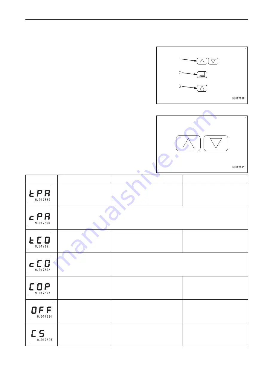
Push button switch
(1) Turn on display
Display values and parameters
Set values and parameters
(2) Change between setting and display mode
Confirm values
(3) Actuation of manual lubrication
Clear fault message
Three-digit LED display
During normal operation, the display is off. It is activated by
briefly operating one of the two push buttons.
It is used for displaying current values and preset parameters.
In addition, the display is used for operator prompting during
setting of operating parameters.
Display
Denotation
Explanation
Control function
t = TIMER
PA = PAUSE
The control unit operates as a time
controlled contact maker (TIMER)
and is in the PAUSE state
Part of lubrication cycle
Input and display value in “hours”
c = COUNTER
PA = PAUSE
Attention! Not used
This mode causes a malfunction.
t = TIMER
CO = CONTACT
The control unit operates as a time
controlled contact maker (TIMER)
and is in the pump running time
(CONTACT)
CONTACT = time during which
the pump is delivering
c = COUNTER
CO = CONTACT
Attention! Not used
This mode causes a malfunction.
C = Cycle
O = OFF
P = Pressure
Display of beginning of menu
“Monitoring settings”
Monitoring
OFF
The monitoring functions PS and
CS are deactivated.
No system monitoring
Cycle Switch
Cycle switch monitoring is activat-
ed.
The cycle switch is monitored for
the transmission of signals dur-
ing the pump running time (CON-
TACT).
OPERATION
EXPLANATION OF COMPONENTS
3-127
Содержание WA480-8
Страница 2: ......
Страница 19: ...Distributor name Address Phone Fax Service personnel FOREWORD PRODUCT INFORMATION 1 17...
Страница 29: ...LOCATION OF SAFETY LABELS SAFETY SAFETY LABELS 2 3...
Страница 69: ...OPERATION Please read and make sure that you understand the SAFETY section before reading this section 3 1...
Страница 76: ...Outside of cab 1 Slow blow fuse 2 Dust indicator 3 Articulation lock pin 4 Toolbox GENERAL VIEW OPERATION 3 8...
Страница 159: ...SWITCHES 1 ECSS switch 2 Front working lamp switch OPERATION EXPLANATION OF COMPONENTS 3 91...
Страница 302: ...Securing position Fixing angle A 61 B 53 C 33 D 38 TRANSPORTATION OPERATION 3 234...
Страница 324: ......
Страница 325: ...MAINTENANCE Please read and make sure that you understand the SAFETY section before reading this section 4 1...
Страница 397: ...Viewed from the rear side of the machine MAINTENANCE MAINTENANCE PROCEDURE 4 73...
Страница 402: ......
Страница 403: ...SPECIFICATIONS 5 1...
Страница 405: ...1 Value when bucket dump angle is 45 B I A G E H F D C 9 J W0 1 4 5 6 SPECIFICATIONS SPECIFICATIONS 5 3...
Страница 406: ......
Страница 422: ......
Страница 423: ...REPLACEMENT PARTS 7 1...
Страница 439: ......
Страница 440: ...WA480 8 WHEEL LOADER Form No VENAM51500 2018 KOMATSU All Rights Reserved Printed in Europe 07 2018...

