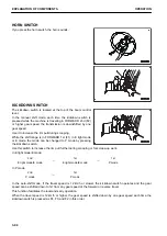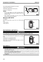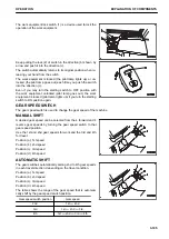
HOLD SWITCH
When HOLD switch on the side face of the boom control lever
knob is pressed to fix the gear speed in the auto-shift mode,
the transmission is fixed to the gear speed indicated on shift in-
dicator (A) of the machine monitor and shift hold pilot lamp (B)
lights up.
When this switch is pressed again, the shift hold function is
canceled and the pilot lamp goes out.
Use this switch to set the gear speed to any position for uphill
or downhill travel or grading.
REMARK
The shift hold function can also be canceled by operating the
directional lever or gear shift switch, or switching the shift mode
to the manual mode with the transmission shift mode selector
switch. It can also be canceled by turning the starting switch to
OFF position.
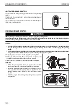
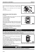
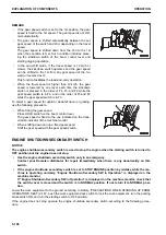
FRONT WIPER SWITCH
If rotary switch (E) of the front wiper switch is rotated, the front
windshield wiper operates.
If push button (F) is pressed, washer fluid is sprinkled on the
front window glass while the push button is held down.
The switch position can be checked by the position of round
mark (G).
Position (A): (OFF) Wiper is stopped.
Position (B): (INT) Wiper moves intermittently.
Position (C): Wiper moves at low speed.
Position (D): Wiper moves at high speed.
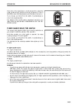
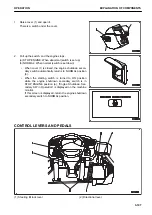
REAR WIPER SWITCH
When turning lever (E) of the rear wiper switch, the rear wiper
operates.
Position (A): Washer fluid is sprayed out. When you release
your hand, it returns to position (B).
Position (B): (OFF) Wiper is stopped.
Position (C): Wiper is actuated.
Position (D): Wiper is actuated and washer fluid is sprayed out.
When you release your hand, the switch returns to position
(C).
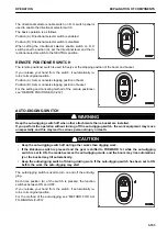
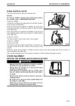
ROOM LAMP SWITCH
NOTICE
If the room lamp is left to be turned on, the batteries may be exhausted. Always turn the switch to OFF
position after using room lamp.
OPERATION
EXPLANATION OF COMPONENTS
3-97
Содержание WA480-8
Страница 2: ......
Страница 19: ...Distributor name Address Phone Fax Service personnel FOREWORD PRODUCT INFORMATION 1 17...
Страница 29: ...LOCATION OF SAFETY LABELS SAFETY SAFETY LABELS 2 3...
Страница 69: ...OPERATION Please read and make sure that you understand the SAFETY section before reading this section 3 1...
Страница 76: ...Outside of cab 1 Slow blow fuse 2 Dust indicator 3 Articulation lock pin 4 Toolbox GENERAL VIEW OPERATION 3 8...
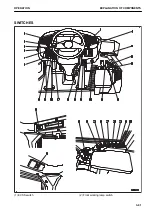
Страница 159: ...SWITCHES 1 ECSS switch 2 Front working lamp switch OPERATION EXPLANATION OF COMPONENTS 3 91...
Страница 302: ...Securing position Fixing angle A 61 B 53 C 33 D 38 TRANSPORTATION OPERATION 3 234...
Страница 324: ......
Страница 325: ...MAINTENANCE Please read and make sure that you understand the SAFETY section before reading this section 4 1...
Страница 397: ...Viewed from the rear side of the machine MAINTENANCE MAINTENANCE PROCEDURE 4 73...
Страница 402: ......
Страница 403: ...SPECIFICATIONS 5 1...
Страница 405: ...1 Value when bucket dump angle is 45 B I A G E H F D C 9 J W0 1 4 5 6 SPECIFICATIONS SPECIFICATIONS 5 3...
Страница 406: ......
Страница 422: ......
Страница 423: ...REPLACEMENT PARTS 7 1...
Страница 439: ......
Страница 440: ...WA480 8 WHEEL LOADER Form No VENAM51500 2018 KOMATSU All Rights Reserved Printed in Europe 07 2018...


