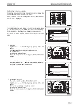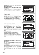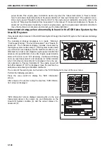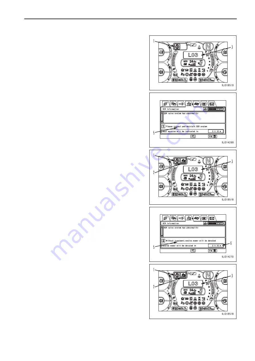
• Warning:
The audible alert sounds in “Intermittent alarm”.
The Engine system caution lamp (1) lights up in red.
The action level “L03” lights up in red at action level dis-
play (3).
Press the menu switch to display the “SCR Information”
screen.
“SCR Information” screen message (5): “1 Please inspect
and maintain SCR system.”
Engine power is derated.
Move the machine to the safe place and contact your Ko-
matsu Distributor.
If operation continues for 5 hour after “Warning” started
without taking any actions instructed by the Action Level
table, Inducement advances to “Continuous Warning”.
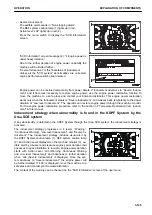
• Continuous Warning:
The audible alert sounds in “Intermittent alarm”.
The Engine system caution lamp (1) lights up in red.
The DEF system caution lamp (2) lights up in yellow.
The action level “L03” lights up in red at action level dis-
play (3).
Press the menu switch to display the “SCR Information”
screen.
“SCR Information” screen message (5): “2 Without treat-
ment, engine power will be derated.”
Move the machine to the safe place and contact your Ko-
matsu Distributor.
The duration time of “Continuous Warning” is 5 hour. The
remaining time (Minutes) till the next Inducement status of
“Low level Inducement” is displayed in the column (6) of
“SCR Information” screen.
In “Low level Inducement”, engine power will be derated.
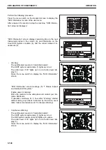
• Low level Inducement:
The audible alert sounds in “Intermittent alarm”.
The Engine system caution lamp (1) lights up in red.
DEF system caution lamp (2) lights up in red.
The action level “L03” lights up in red at action level dis-
play (3).
Press the menu switch to display the “SCR Information”
screen.
OPERATION
EXPLANATION OF COMPONENTS
3-149
Содержание WA480-8
Страница 2: ......
Страница 19: ...Distributor name Address Phone Fax Service personnel FOREWORD PRODUCT INFORMATION 1 17...
Страница 29: ...LOCATION OF SAFETY LABELS SAFETY SAFETY LABELS 2 3...
Страница 69: ...OPERATION Please read and make sure that you understand the SAFETY section before reading this section 3 1...
Страница 76: ...Outside of cab 1 Slow blow fuse 2 Dust indicator 3 Articulation lock pin 4 Toolbox GENERAL VIEW OPERATION 3 8...
Страница 159: ...SWITCHES 1 ECSS switch 2 Front working lamp switch OPERATION EXPLANATION OF COMPONENTS 3 91...
Страница 302: ...Securing position Fixing angle A 61 B 53 C 33 D 38 TRANSPORTATION OPERATION 3 234...
Страница 324: ......
Страница 325: ...MAINTENANCE Please read and make sure that you understand the SAFETY section before reading this section 4 1...
Страница 397: ...Viewed from the rear side of the machine MAINTENANCE MAINTENANCE PROCEDURE 4 73...
Страница 402: ......
Страница 403: ...SPECIFICATIONS 5 1...
Страница 405: ...1 Value when bucket dump angle is 45 B I A G E H F D C 9 J W0 1 4 5 6 SPECIFICATIONS SPECIFICATIONS 5 3...
Страница 406: ......
Страница 422: ......
Страница 423: ...REPLACEMENT PARTS 7 1...
Страница 439: ......
Страница 440: ...WA480 8 WHEEL LOADER Form No VENAM51500 2018 KOMATSU All Rights Reserved Printed in Europe 07 2018...


