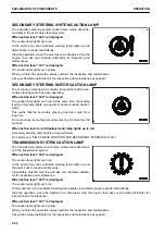

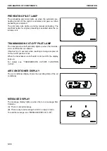
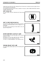


SHIFT HOLD PILOT LAMP
The shift hold pilot lamp lights up when the shift hold function
works.
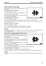
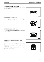
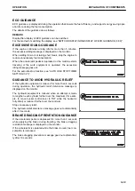
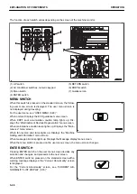
TORQUE CONVERTER LOCKUP MODE DISPLAY
The torque converter lockup pilot lamp displays the set state of
the torque converter lockup mode.
By selecting torque converter lockup mode selector switch, one
of the following lamps lights up.
(A): Lockup mode ON
(B): Lockup mode OFF
When the mode is changed, the display pops up.
For selection of the lockup function mode, see “HANDLE TOR-
QUE CONVERTER LOCKUP (3-200)”.
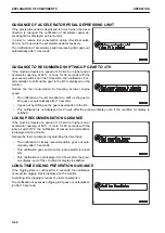
AUTOMATIC SHIFT PILOT LAMP
The automatic shift pilot lamp lights up when the auto-shift
function is selected.
Change the shift mode with the transmission shift mode selec-
tor switch.
When the shift mode is changed from manual to auto, the dis-
play pops up.
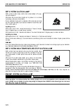
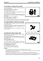
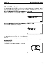
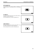
FAN REVERSE ROTATION DISPLAY
When the radiator fan is set in manual or auto reverse rotation
mode, if the fan starts to rotate in reverse, fan reverse rotation
pilot lamp (A) lights up.
This lamp flashes while the rotation direction is being changed.
If the condition for changing the fan rotation direction is not sat-
isfied, changing condition satisfaction waiting pilot lamp (B)
lights up.
For details of the method of setting the fan reverse mode, see
“RADIATOR FAN MANUAL REVERSE MODE (3-62)” and
“RADIATOR FAN AUTOMATIC REVERSE MODE (3-64)”.
OPERATION
EXPLANATION OF COMPONENTS
3-35
Содержание WA480-8
Страница 2: ......
Страница 19: ...Distributor name Address Phone Fax Service personnel FOREWORD PRODUCT INFORMATION 1 17...
Страница 29: ...LOCATION OF SAFETY LABELS SAFETY SAFETY LABELS 2 3...
Страница 69: ...OPERATION Please read and make sure that you understand the SAFETY section before reading this section 3 1...
Страница 76: ...Outside of cab 1 Slow blow fuse 2 Dust indicator 3 Articulation lock pin 4 Toolbox GENERAL VIEW OPERATION 3 8...
Страница 159: ...SWITCHES 1 ECSS switch 2 Front working lamp switch OPERATION EXPLANATION OF COMPONENTS 3 91...
Страница 302: ...Securing position Fixing angle A 61 B 53 C 33 D 38 TRANSPORTATION OPERATION 3 234...
Страница 324: ......
Страница 325: ...MAINTENANCE Please read and make sure that you understand the SAFETY section before reading this section 4 1...
Страница 397: ...Viewed from the rear side of the machine MAINTENANCE MAINTENANCE PROCEDURE 4 73...
Страница 402: ......
Страница 403: ...SPECIFICATIONS 5 1...
Страница 405: ...1 Value when bucket dump angle is 45 B I A G E H F D C 9 J W0 1 4 5 6 SPECIFICATIONS SPECIFICATIONS 5 3...
Страница 406: ......
Страница 422: ......
Страница 423: ...REPLACEMENT PARTS 7 1...
Страница 439: ......
Страница 440: ...WA480 8 WHEEL LOADER Form No VENAM51500 2018 KOMATSU All Rights Reserved Printed in Europe 07 2018...


