1.
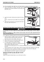
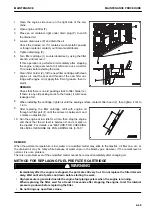
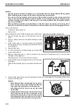
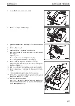
Open the cover of the battery box.
One each of the battery box is provided on both sides of
the rear part of the machine.
2.
Clean around the electrolyte level line with a cloth wet with
water.
Check that the electrolyte level is between UPPER LEVEL
(U.L.) line and LOWER LEVEL (L.L.) line.
3.
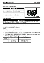
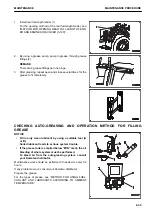
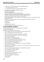
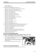
When the electrolyte level is below the center between
UPPER LEVEL (U.L.) and LOWER LEVEL (L.L.), remove
cap (1) immediately.
4.
Add purified water (example: commercially available battery liquid) up to UPPER LEVEL (U.L.)
5.
When you add the purified water to the cell of cap (1), add
it to other cells as well.
6.
Clean the vent hole of the battery cap, then close the cap
securely.
Keep the battery top surface clean and wipe off dirt on it
using a wet cloth.
REMARK
If purified water is added to above the UPPER LEVEL
(U.L.) line, use a syringe to lower the level to the UPPER
LEVEL (U.L.) line. Neutralize the removed fluid with baking
soda (sodium bicarbonate), then flush it away with a large
amount of water. If necessary, consult your Komatsu dis-
tributor or a battery manufacturer.
METHOD FOR CHECKING ELECTROLYTE LEVEL WHEN IT IS IMPOSSIBLE TO
CHECK FROM SIDE OF BATTERY
If it is impossible to check the electrolyte level from the side of the battery, or there is no UPPER LEVEL line on
the side of the battery, check according to the following procedures.
1.
Open the cover of the battery box.
One each of the battery box is provided on both sides of the rear part of the machine.
2.
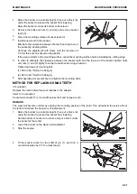
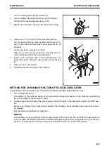
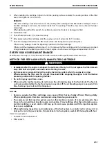
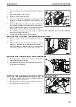
Remove cap (1) at the top of the battery and check the
electrolyte level through electrolyte filler port (2).
3.
If the electrolyte does not reach the sleeve (3), always add
the purified water (e.g. commercially available replenish-
ment water for a battery) so that the level reaches the bot-
tom of the sleeve (UPPER LEVEL line).
• (A) Correct level: Electrolyte level is up to bottom of
sleeve, so surface tension causes electrolyte surface
to bulge and pole plate appears to be warped.
• (B) Low level: Electrolyte level does not reach the bot-
tom of sleeve, so pole plate appears straight and not
to be warped.
4.
When you add the purified water to the cell of cap (1), add
it to other cells as well.
5.
After adding the purified water, tighten cap (1) securely.
MAINTENANCE PROCEDURE
MAINTENANCE
4-44
Содержание WA480-8
Страница 2: ......
Страница 19: ...Distributor name Address Phone Fax Service personnel FOREWORD PRODUCT INFORMATION 1 17...
Страница 29: ...LOCATION OF SAFETY LABELS SAFETY SAFETY LABELS 2 3...
Страница 69: ...OPERATION Please read and make sure that you understand the SAFETY section before reading this section 3 1...
Страница 76: ...Outside of cab 1 Slow blow fuse 2 Dust indicator 3 Articulation lock pin 4 Toolbox GENERAL VIEW OPERATION 3 8...
Страница 159: ...SWITCHES 1 ECSS switch 2 Front working lamp switch OPERATION EXPLANATION OF COMPONENTS 3 91...
Страница 302: ...Securing position Fixing angle A 61 B 53 C 33 D 38 TRANSPORTATION OPERATION 3 234...
Страница 324: ......
Страница 325: ...MAINTENANCE Please read and make sure that you understand the SAFETY section before reading this section 4 1...
Страница 397: ...Viewed from the rear side of the machine MAINTENANCE MAINTENANCE PROCEDURE 4 73...
Страница 402: ......
Страница 403: ...SPECIFICATIONS 5 1...
Страница 405: ...1 Value when bucket dump angle is 45 B I A G E H F D C 9 J W0 1 4 5 6 SPECIFICATIONS SPECIFICATIONS 5 3...
Страница 406: ......
Страница 422: ......
Страница 423: ...REPLACEMENT PARTS 7 1...
Страница 439: ......
Страница 440: ...WA480 8 WHEEL LOADER Form No VENAM51500 2018 KOMATSU All Rights Reserved Printed in Europe 07 2018...

