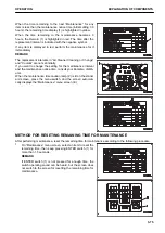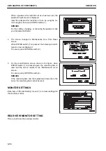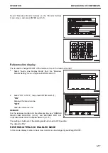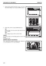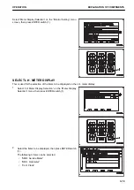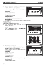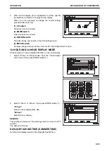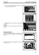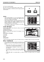
(A): There is unread message.
(B): There is any read message to which no reply is made.
Reply to the message in accordance with the replying method
mentioned later.
REMARK
• While message display (1) is lit on the standard screen,
when menu switch (2) is pressed, User Message menu
screen (G) is displayed automatically.
• When the starting switch is turned OFF while there is any
unread message, the message is displayed on the end
screen, and when the monitor is started next time, the
message changes to a read message.
• The message is deleted when it becomes out of date or
when a new message reaches.
CHECK MESSAGE
Select message display menu screen (G), and you can read
the arrived message.
(A) Subject of message
When no message has been received, “No message.” is dis-
played.
(B) Serial No. of message
(C) Validity
(D) Text
(E) Reply field
In case of a message requesting for reply, the “Numeric Input: [ ]” is displayed. Make any reply to the message.
REPLY TO MESSAGE
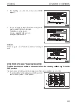
1.
When replying to a message, input the selected item num-
ber shown in the text of the message by using the switch
panel.
• Each switch of the switch panel corresponds to the
number shown on the lower right of the switch.
• The input number is displayed in “Numeric Input: [ ]”of
the reply field.
• If you input an incorrect number, press RETURN
switch (1), and you can clear an input character at a
time.
• If RETURN switch (1) is pressed while no number is entered, the display returns to the standard
screen.
EXPLANATION OF COMPONENTS
OPERATION
3-88
Содержание WA480-8
Страница 2: ......
Страница 19: ...Distributor name Address Phone Fax Service personnel FOREWORD PRODUCT INFORMATION 1 17...
Страница 29: ...LOCATION OF SAFETY LABELS SAFETY SAFETY LABELS 2 3...
Страница 69: ...OPERATION Please read and make sure that you understand the SAFETY section before reading this section 3 1...
Страница 76: ...Outside of cab 1 Slow blow fuse 2 Dust indicator 3 Articulation lock pin 4 Toolbox GENERAL VIEW OPERATION 3 8...
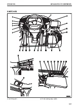
Страница 159: ...SWITCHES 1 ECSS switch 2 Front working lamp switch OPERATION EXPLANATION OF COMPONENTS 3 91...
Страница 302: ...Securing position Fixing angle A 61 B 53 C 33 D 38 TRANSPORTATION OPERATION 3 234...
Страница 324: ......
Страница 325: ...MAINTENANCE Please read and make sure that you understand the SAFETY section before reading this section 4 1...
Страница 397: ...Viewed from the rear side of the machine MAINTENANCE MAINTENANCE PROCEDURE 4 73...
Страница 402: ......
Страница 403: ...SPECIFICATIONS 5 1...
Страница 405: ...1 Value when bucket dump angle is 45 B I A G E H F D C 9 J W0 1 4 5 6 SPECIFICATIONS SPECIFICATIONS 5 3...
Страница 406: ......
Страница 422: ......
Страница 423: ...REPLACEMENT PARTS 7 1...
Страница 439: ......
Страница 440: ...WA480 8 WHEEL LOADER Form No VENAM51500 2018 KOMATSU All Rights Reserved Printed in Europe 07 2018...


