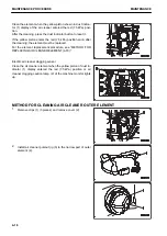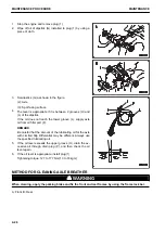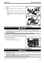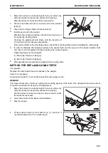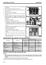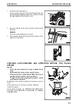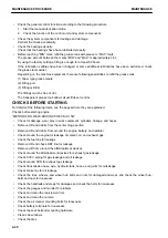
For soil and dust fallen down, blow them out of the machine according to the following procedure.
4.
Loosen wing bolts (4) (2 pieces), and slide covers for
cleaning (5) on the right and left sides of the machine, and
open those covers.
5.
Insert the air nozzle, and blow dust out forward of the ma-
chine.
Steam or water may be used instead of the compressed
air.
6.
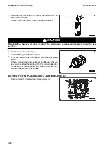
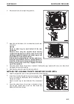
Install covers for cleaning (5) on the right and left side of
the machine after blowing dust out.
METHOD FOR INVERTING AND REPLACING BOLT ON CUTTING EDGE
k
k
WARNING
It is dangerous if the work equipment moves by mistake when the cutting edge or end bit is being re-
placed.
Set the work equipment in a stable condition, stop the engine, then lock the work equipment (the pilot
lamp in the switch lights up).
Turn or replace the cutting edge before the wear reaches the edge of the bucket.
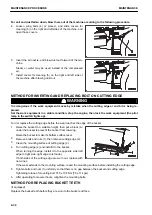
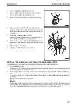
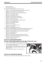
1.
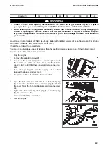
Raise the bucket to a suitable height, then put a block (A)
under the bucket to prevent the bucket from lowering.
Raise the bucket to make its bottom surface level.
2.
Remove bolts and nuts (1), then remove cutting edge (2).
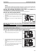
3.
Clean the mounting surface of cutting edge (2).
4.
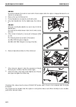
Turn cutting edge (2) and install it to the bucket.
When turning the edge, install it to the opposite side (left
edge to right side, right edge to left side).
If both sides of the cutting edge are worn out, replace with
new ones.
If the wear extends to the mounting surface, repair the mounting surface before installing the cutting edge.
5.
Tighten bolts and nuts (1) uniformly so that there is no gap between the bucket and cutting edge.
Tightening torque of mounting bolt: 745 ± 108 Nm {76 ± 11 kgm}
6.
After operating for several hours, retighten the mounting bolts.
METHOD FOR REPLACING BUCKET TEETH
(if equipped)
Replace the bucket teeth before they are worn to the bucket end face.
MAINTENANCE PROCEDURE
MAINTENANCE
4-30
Содержание WA480-8
Страница 2: ......
Страница 19: ...Distributor name Address Phone Fax Service personnel FOREWORD PRODUCT INFORMATION 1 17...
Страница 29: ...LOCATION OF SAFETY LABELS SAFETY SAFETY LABELS 2 3...
Страница 69: ...OPERATION Please read and make sure that you understand the SAFETY section before reading this section 3 1...
Страница 76: ...Outside of cab 1 Slow blow fuse 2 Dust indicator 3 Articulation lock pin 4 Toolbox GENERAL VIEW OPERATION 3 8...
Страница 159: ...SWITCHES 1 ECSS switch 2 Front working lamp switch OPERATION EXPLANATION OF COMPONENTS 3 91...
Страница 302: ...Securing position Fixing angle A 61 B 53 C 33 D 38 TRANSPORTATION OPERATION 3 234...
Страница 324: ......
Страница 325: ...MAINTENANCE Please read and make sure that you understand the SAFETY section before reading this section 4 1...
Страница 397: ...Viewed from the rear side of the machine MAINTENANCE MAINTENANCE PROCEDURE 4 73...
Страница 402: ......
Страница 403: ...SPECIFICATIONS 5 1...
Страница 405: ...1 Value when bucket dump angle is 45 B I A G E H F D C 9 J W0 1 4 5 6 SPECIFICATIONS SPECIFICATIONS 5 3...
Страница 406: ......
Страница 422: ......
Страница 423: ...REPLACEMENT PARTS 7 1...
Страница 439: ......
Страница 440: ...WA480 8 WHEEL LOADER Form No VENAM51500 2018 KOMATSU All Rights Reserved Printed in Europe 07 2018...

