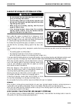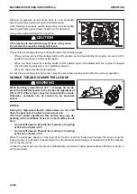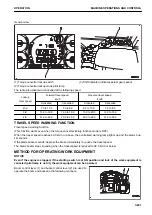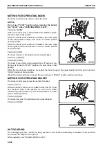
NOTICE
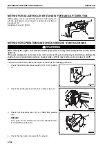
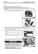
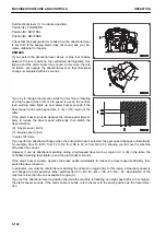
Turn the steering wheel a little and stop in that position. Check that the machine has turned by the
angle corresponding to the turning angle of the steering wheel.
5.
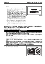
After the warm-up operation, check that the instruments
and pilot lamps are normal.
If any problem is found, perform maintenance or repair.
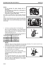
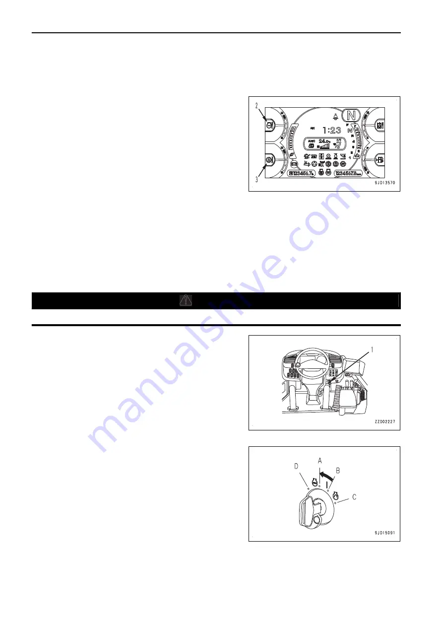
Run the engine with a light load until the pointers of engine
coolant temperature gauge (2) and torque converter oil
temperature gauge (3) indicate the green range.
6.
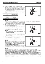
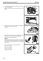
Check for abnormal exhaust gas color, noise, or vibration.
If any abnormality is found, contact your Komatsu distribu-
tor.
REMARK
The cooling fan speed varies according to the following
conditions, but it is not abnormal.
The cooling fan speed increases when the hydraulic oil
temperature , engine coolant temperature, or transmission
oil temperature is high.
when the cooling fan is rotating in reverse, it rotates at a
fixed speed in proportion to the engine speed, regardless
of any oil or coolant temperature.
METHOD FOR STOPPING ENGINE
k
k
WARNING
Keep away from the exhaust pipe immediately after stopping the engine.
NOTICE
If the engine is abruptly stopped before it has cooled
down, service life of the engine parts may be reduced. Do
not stop the engine abruptly except the case in an emer-
gency.
If the engine is overheated, do not try to stop it abruptly
but run it at medium speed to allow it to cool down gradu-
ally, and then stop it.
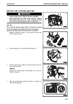
Stop the engine according to the following procedure.
1.
Run the engine at low idle for approximately 5 minutes to cool down the engine gradually.
2.
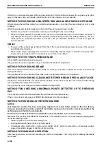
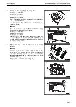
Turn the key of starting switch (1) to OFF position (A), and
stop the engine.
3.
Remove the key from starting switch (1).
MACHINE OPERATIONS AND CONTROLS
OPERATION
3-188
Содержание WA480-8
Страница 2: ......
Страница 19: ...Distributor name Address Phone Fax Service personnel FOREWORD PRODUCT INFORMATION 1 17...
Страница 29: ...LOCATION OF SAFETY LABELS SAFETY SAFETY LABELS 2 3...
Страница 69: ...OPERATION Please read and make sure that you understand the SAFETY section before reading this section 3 1...
Страница 76: ...Outside of cab 1 Slow blow fuse 2 Dust indicator 3 Articulation lock pin 4 Toolbox GENERAL VIEW OPERATION 3 8...
Страница 159: ...SWITCHES 1 ECSS switch 2 Front working lamp switch OPERATION EXPLANATION OF COMPONENTS 3 91...
Страница 302: ...Securing position Fixing angle A 61 B 53 C 33 D 38 TRANSPORTATION OPERATION 3 234...
Страница 324: ......
Страница 325: ...MAINTENANCE Please read and make sure that you understand the SAFETY section before reading this section 4 1...
Страница 397: ...Viewed from the rear side of the machine MAINTENANCE MAINTENANCE PROCEDURE 4 73...
Страница 402: ......
Страница 403: ...SPECIFICATIONS 5 1...
Страница 405: ...1 Value when bucket dump angle is 45 B I A G E H F D C 9 J W0 1 4 5 6 SPECIFICATIONS SPECIFICATIONS 5 3...
Страница 406: ......
Страница 422: ......
Страница 423: ...REPLACEMENT PARTS 7 1...
Страница 439: ......
Страница 440: ...WA480 8 WHEEL LOADER Form No VENAM51500 2018 KOMATSU All Rights Reserved Printed in Europe 07 2018...

