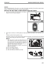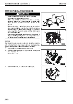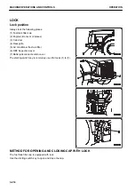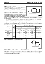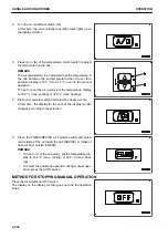
2.
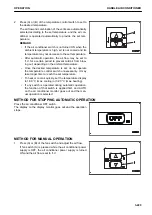
Press (A) or (B) of the temperature control switch to set to
the desired temperature.
The air flow and combination of the vents are automatically
selected according to the set temperature, and the air con-
ditioner is operated automatically to provide the set tem-
perature.
REMARK
• If the air conditioner switch is not turned ON when the
ambient temperature is high, air is not cooled and its
temperature may not decrease to the set temperature.
• After automatic operation, the air flow may be set to
“Lo” for a certain period to prevent cold air from blow-
ing out, depending on the ambient temperature.
• Once the desired temperature is set, do not operate
the temperature control switch unnecessarily. It may
take longer time to reach the set temperature.
• To heat or cool air quickly, set the temperature display
to 18.0 °C (max. cooling) or 32.0 °C (max. heating).
• If any switch is operated during automatic operation,
the function of that switch is applied first, and AUTO
on the air conditioner monitor goes out and the man-
ual operation is selected.
METHOD FOR STOPPING AUTOMATIC OPERATION
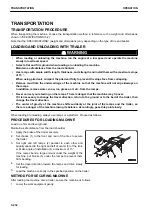
Press the air conditioner OFF switch.
The display on the display monitor goes out and the operation
stops.
METHOD FOR MANUAL OPERATION
1.
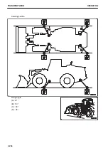
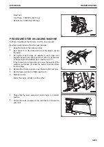
Press (A) or (B) of the fan switch and adjust the air flow.
If fan switch (A) is pressed while the air conditioner power
supply is OFF, the air conditioner power supply is turned
ON and the air flow is set to “Lo”.
OPERATION
HANDLE AIR CONDITIONER
3-229
Содержание WA480-8
Страница 2: ......
Страница 19: ...Distributor name Address Phone Fax Service personnel FOREWORD PRODUCT INFORMATION 1 17...
Страница 29: ...LOCATION OF SAFETY LABELS SAFETY SAFETY LABELS 2 3...
Страница 69: ...OPERATION Please read and make sure that you understand the SAFETY section before reading this section 3 1...
Страница 76: ...Outside of cab 1 Slow blow fuse 2 Dust indicator 3 Articulation lock pin 4 Toolbox GENERAL VIEW OPERATION 3 8...
Страница 159: ...SWITCHES 1 ECSS switch 2 Front working lamp switch OPERATION EXPLANATION OF COMPONENTS 3 91...
Страница 302: ...Securing position Fixing angle A 61 B 53 C 33 D 38 TRANSPORTATION OPERATION 3 234...
Страница 324: ......
Страница 325: ...MAINTENANCE Please read and make sure that you understand the SAFETY section before reading this section 4 1...
Страница 397: ...Viewed from the rear side of the machine MAINTENANCE MAINTENANCE PROCEDURE 4 73...
Страница 402: ......
Страница 403: ...SPECIFICATIONS 5 1...
Страница 405: ...1 Value when bucket dump angle is 45 B I A G E H F D C 9 J W0 1 4 5 6 SPECIFICATIONS SPECIFICATIONS 5 3...
Страница 406: ......
Страница 422: ......
Страница 423: ...REPLACEMENT PARTS 7 1...
Страница 439: ......
Страница 440: ...WA480 8 WHEEL LOADER Form No VENAM51500 2018 KOMATSU All Rights Reserved Printed in Europe 07 2018...

