REMARK
When setting RAISE detent, if the boom is very close to the position specified by the positioner (approximately
within 2 °), the boom control lever does not set to the detent position.
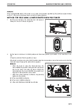
METHOD FOR RELEASING LOWER REMOTE BOOM POSITIONER
1.
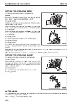
Set the boom between the horizontal level and approxi-
mately 30 cm or more above the ground.
2.
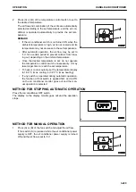
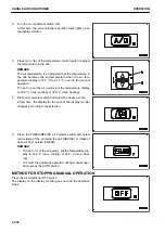
Set the boom control lever to HOLD position and hold down position (a) of switch (1) for more than 1 sec-
ond.
A “beep” sounds and the stop position is reset.
If the boom control lever is set to FLOAT position while the stop position is reset, the boom is set to the float
mode and moved freely by the external force applied.
REMARK
• When the boom is above the horizontal level, the
boom RAISE stop position setting and its reset opera-
tion can be made. And when the boom is below the
horizontal level, the boom LOWER stop position set-
ting and its reset operation can be made.
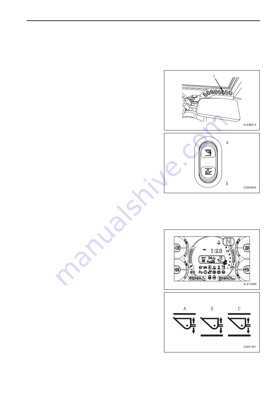
• When the remote positioner is effective, the pilot lamp
lights up in the monitor.
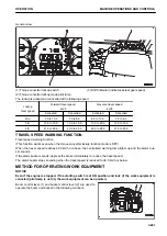
(A): When only RAISE is effective
(B): When only LOWER is effective
(C): When both RAISE and LOWER are effective
OPERATION
MACHINE OPERATIONS AND CONTROLS
3-215
Содержание WA480-8
Страница 2: ......
Страница 19: ...Distributor name Address Phone Fax Service personnel FOREWORD PRODUCT INFORMATION 1 17...
Страница 29: ...LOCATION OF SAFETY LABELS SAFETY SAFETY LABELS 2 3...
Страница 69: ...OPERATION Please read and make sure that you understand the SAFETY section before reading this section 3 1...
Страница 76: ...Outside of cab 1 Slow blow fuse 2 Dust indicator 3 Articulation lock pin 4 Toolbox GENERAL VIEW OPERATION 3 8...
Страница 159: ...SWITCHES 1 ECSS switch 2 Front working lamp switch OPERATION EXPLANATION OF COMPONENTS 3 91...
Страница 302: ...Securing position Fixing angle A 61 B 53 C 33 D 38 TRANSPORTATION OPERATION 3 234...
Страница 324: ......
Страница 325: ...MAINTENANCE Please read and make sure that you understand the SAFETY section before reading this section 4 1...
Страница 397: ...Viewed from the rear side of the machine MAINTENANCE MAINTENANCE PROCEDURE 4 73...
Страница 402: ......
Страница 403: ...SPECIFICATIONS 5 1...
Страница 405: ...1 Value when bucket dump angle is 45 B I A G E H F D C 9 J W0 1 4 5 6 SPECIFICATIONS SPECIFICATIONS 5 3...
Страница 406: ......
Страница 422: ......
Страница 423: ...REPLACEMENT PARTS 7 1...
Страница 439: ......
Страница 440: ...WA480 8 WHEEL LOADER Form No VENAM51500 2018 KOMATSU All Rights Reserved Printed in Europe 07 2018...

