The battery disconnect switch is used to cut out the electricity
from the battery.
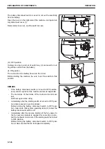
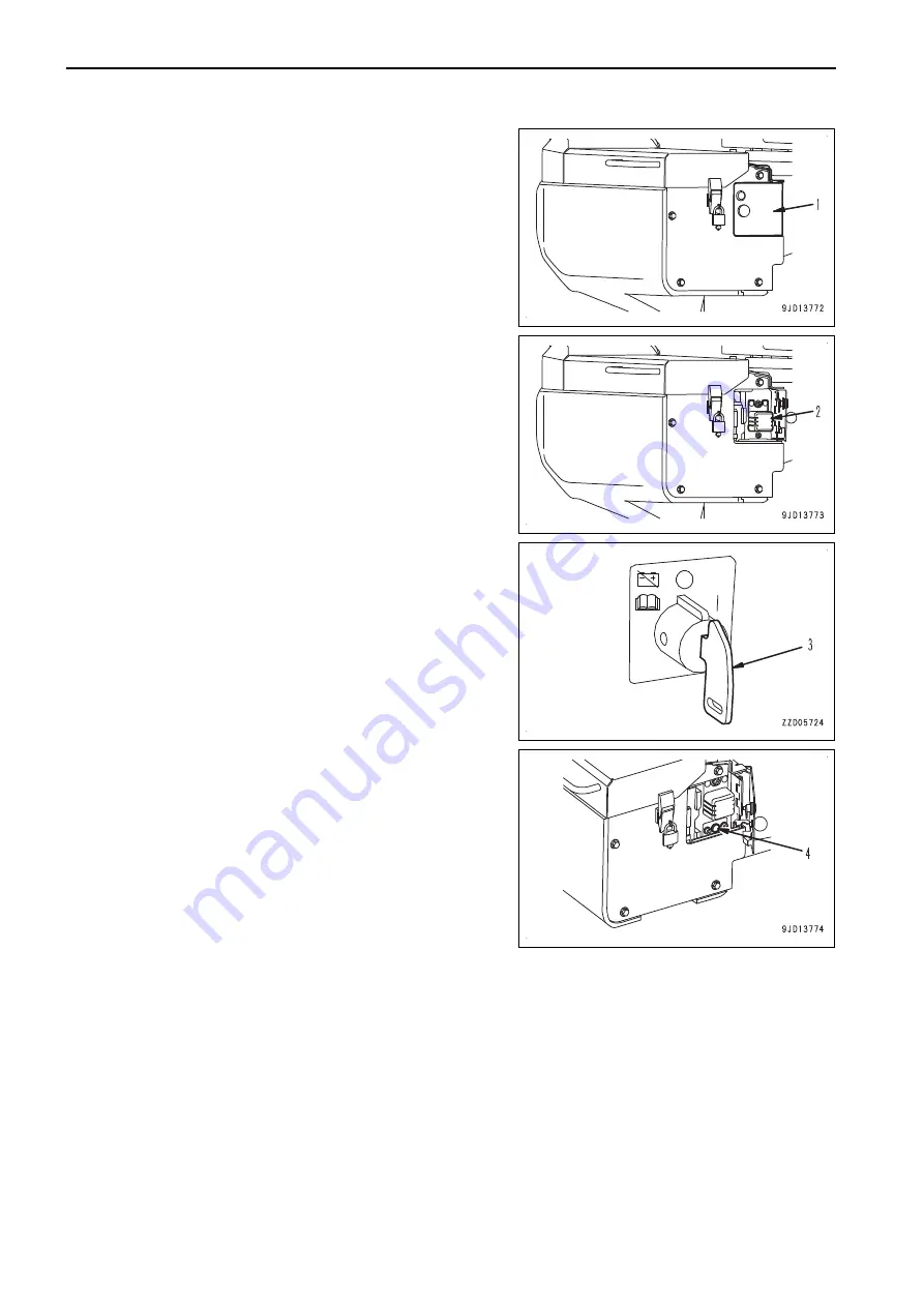
Open the cover on the right side of the machine, and open bat-
tery disconnect cover (1).
Raise rubber cover (2), and the switch is seen.
(O): OFF position
It allows moving in and out of switch key (3) and used for cut-
ting off the current from the battery.
(I): ON position
The current from the battery flows into the circuit.
Before starting the machine, be sure to set the switch to this
position.
REMARK
• If the battery disconnect switch is turned to OFF position,
every electric system of the machine becomes inoperable.
• The memories of the clocks of the radio and monitor are
lost.
Set them again when using.
• Immediately after the starting switch is turned to OFF posi-
tion, data is saved on each controller.
Before turning the battery disconnect switch to OFF posi-
tion, make sure that system operating lamp (4) below the
battery disconnect switch is off.
• Immediately after the reverse rotation of the fan, power to
the fan reverse solenoid is supplied for some time to pro-
tect the hydraulic motor even if the starting switch is turned
to OFF position.
Before turning the battery disconnect switch to OFF posi-
tion, make sure that the fan is stopped completely.
EXPLANATION OF COMPONENTS
OPERATION
3-124
Содержание WA480-8
Страница 2: ......
Страница 19: ...Distributor name Address Phone Fax Service personnel FOREWORD PRODUCT INFORMATION 1 17...
Страница 29: ...LOCATION OF SAFETY LABELS SAFETY SAFETY LABELS 2 3...
Страница 69: ...OPERATION Please read and make sure that you understand the SAFETY section before reading this section 3 1...
Страница 76: ...Outside of cab 1 Slow blow fuse 2 Dust indicator 3 Articulation lock pin 4 Toolbox GENERAL VIEW OPERATION 3 8...
Страница 159: ...SWITCHES 1 ECSS switch 2 Front working lamp switch OPERATION EXPLANATION OF COMPONENTS 3 91...
Страница 302: ...Securing position Fixing angle A 61 B 53 C 33 D 38 TRANSPORTATION OPERATION 3 234...
Страница 324: ......
Страница 325: ...MAINTENANCE Please read and make sure that you understand the SAFETY section before reading this section 4 1...
Страница 397: ...Viewed from the rear side of the machine MAINTENANCE MAINTENANCE PROCEDURE 4 73...
Страница 402: ......
Страница 403: ...SPECIFICATIONS 5 1...
Страница 405: ...1 Value when bucket dump angle is 45 B I A G E H F D C 9 J W0 1 4 5 6 SPECIFICATIONS SPECIFICATIONS 5 3...
Страница 406: ......
Страница 422: ......
Страница 423: ...REPLACEMENT PARTS 7 1...
Страница 439: ......
Страница 440: ...WA480 8 WHEEL LOADER Form No VENAM51500 2018 KOMATSU All Rights Reserved Printed in Europe 07 2018...


