background image

Komatsu has had the operating and maintenance instructions

translated into all the languages of the European Union.

Should you require a copy in another language please inquire

at your local dealer’s

.

Operation & Maintenance
Manual

Incorrect operation and maintenance of this machine
may be hazardous and cause injuries. The operator and
maintenance personnel must read this manual before
commencing operation or maintenance. Keep this
manual within reach at all times and ensure that
operating personnel read it at regular intervals.

SERIAL NUMBERS WA320H50051 AND UP

-5H

VEAM240100

WHEEL LOADER

NOTE

DANGER

Содержание WA320-5H

Страница 1: ...peration Maintenance Manual Incorrect operation and maintenance of this machine may be hazardous and cause injuries The operator and maintenance personnel must read this manual before commencing opera...

Страница 2: ...FOREWORD 11...

Страница 3: ...you understand them fully Keep this manual at the storage location for the Operation and Maintenance Manual given below and have all personnel read it periodically If this manual has been lost or has...

Страница 4: ...observed If you are installing electrical or electronic equipment and or components in the machine and connect them to the vehicle electrical system you must check at own responsibility that the inst...

Страница 5: ...ituation which if not avoided could result in death or serious injury Indicates a potentially hazardous situation which if not avoided may result in minor or mod erate injury This word is used also to...

Страница 6: ...ng the hazardous condition is shown inside a circle Komatsu cannot predict every circumstance that might involve a potential hazard in operation and maintenance Therefore the safety messages in this m...

Страница 7: ...not accept any responsibility for safety All considerations concerning safety will then be up to the owner or the operating and maintenance personnel In any case neither you nor any other person are i...

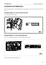
Страница 8: ...t parts please inform your Komatsu distributor of the following items MACHINE SERIAL NO PLATE AND POSITION 1 On the center right of the front frame ENGINE SERIAL NO PLATE AND POSITION 1 This is on the...

Страница 9: ...the rear beam AXLE SERIAL NO PLATE This plate is located on the right of front axle and on the left of rear axle TRANSMISSION SERIAL NO PLATE This plate is located in travel direction front above the...

Страница 10: ...ORMATION 1 9 POSITION OF SERVICE METER 1 It is at the center bottom of the machine monitor TABLE TO ENTER SERIAL NO AND DISTRIBUTOR 1 Machine serial No Engine serial No Distributor name Address Servic...

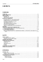
Страница 11: ...ERATING DATA 1 17 WA320 5H DIMENSIONS WEIGHTS AND OPERATING DATA 1 17 CE CONFORMING EQUIPMENT 1 18 CE CONFORMING EQUIPMENT 1 18 MANUFACTURER SUPPLIED CE CONFORMING EQUIPMENT ACCORDING TO DOCUMENT 421...

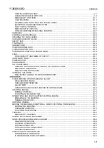
Страница 12: ...3 52 PRECAUTIONS WHEN USING 3 53 HANDLING CAB WIPER 3 53 PREVENTING DAMAGE TO WIPER ARM BRACKET 3 53 OPERATION 3 54 CHECK BEFORE STARTING ENGINE ADJUST 3 54 WALK AROUND CHECK 3 54 CHECK BEFORE STARTI...

Страница 13: ...LD WEATHER OPERATION 3 107 PRECAUTIONS FOR LOW TEMPERATURE 3 107 FUEL AND LUBRICANTS 3 107 COOLANT 3 107 BATTERY 3 108 PRECAUTIONS AFTER COMPLETION OF WORK 3 108 AFTER COLD WEATHER 3 109 WARMING UP OP...

Страница 14: ...COOLER FINS 4 30 CLEAN TRANSFER OIL COOLER FINS 4 31 CHECK ELECTRICAL INTAKE AIR HEATER 4 31 REPLACE BOLT ON CUTTING EDGE 4 32 REPLACE BUCKET TEETH 4 33 CHECK AIR CONDITIONER 4 34 REPLACE SLOW BLOW F...

Страница 15: ...5 4 VIBRATION LEVEL 5 4 ATTACHMENTS OPTIONS SELECTING BUCKET AND TIRES 6 2 MACHINE MONITOR WITH LOAD METER 6 3 EXPLANATION OF COMPONENTS 6 3 MACHINE MONITOR 6 3 MONITOR PANEL MODE SELECTOR SWITCH 1 6...

Страница 16: ...5 CENTRAL LUBRICATION SYSTEM 6 63 OPERATING THE CENTRAL LUBRICATION SYSTEM 6 63 DISPLAY AND CONTROL UNIT 6 63 LED DISPLAY 6 64 PUSHBUTTONS 6 64 CHANGING THE LUBRICATION INTERVAL TIMES 6 65 INDEX INDEX...

Страница 17: ...CONTENTS FOREWORD 1 16...

Страница 18: ...ic kN 134 Lifting capacity hydraulic on ground kN 155 Operating weight kg 14 040 a Reach at 45 discharge mm 990 b Dumping height at 45 discharge mm 2 855 c Lift height hinge pin mm 3 910 d Height to u...

Страница 19: ...5 Type Part No Volume m Load Capacity kg Hydraulic pressure bar Weight kg Bucket WA320 5H 419 72 H2100 2 7 1 040 419 72 H2110 2 7 1 143 419 72 H2160 2 7 1 118 419 72 H2170 2 7 2 217 419 72 H2120 2 85...

Страница 20: ...ve been fulfilled when the manufacturer of the equipment confirms fulfilment of the form 421 93 H1900 along side The certification must be sent to the customer and the wheel loader manufacturer The CE...

Страница 21: ...CE CONFORMING EQUIPMENT FOREWORD 1 20 D1 C1 B1 1 D2 C2 B2 Sh H1 H2 J 2 Sh A2 A1 G d1 d2 3 3 b3 b4 b1 b2 e d2 h c d1 GK100395...

Страница 22: ...re front axle horizontal D2 Distance headlight centre front axle vertical G Weight of equipment and working load H1 Distance bucket pivoting point bucket upper edge verti cal carrying position H2 Dist...

Страница 23: ...CE CONFORMING EQUIPMENT FOREWORD 1 22...

Страница 24: ...SAFETY 12...

Страница 25: ...SAFETY 2 2...

Страница 26: ...ect position and content of these safety labels Always keep all safety labels clean When cleaning them use soap and water Do not use organic solvents or gas oline These may cause the safety labels to...

Страница 27: ...ec tion maintenance or transportation Sign indicates a hazard of unexpected moving of stopped machine Lower working device to ground move safety lever to lock position and take engine key with you bef...

Страница 28: ...ns when oil is at high temperature 421 93 H1280 Sign indicates a burn hazard from spurting hot water if radiator is uncapped while hot Allow coolant to cool before removing cap Sign indicates a burn h...

Страница 29: ...re inspection and mainte nance 13 Do not come under machine sign 421 93 H1370 14 Do not go under work equipment sign 421 93 H1380 Sign indicates a hazard of being run over by moving vehicle Keep a saf...

Страница 30: ...CTIVE ITEMS q Do not wear loose clothing and accessories There is a hazard that they may catch on control levers or other protruding parts q If you have long hair and it hangs out from your hard hat t...

Страница 31: ...e machine is still dirty with mud or oil there is a hazard that you will slip and fall or that dirt or mud will get into your eyes Always keep the machine clean INSIDE OPERATOR S COMPARTMENT q When en...

Страница 32: ...ay suddenly move and cause serious injury or property damage q When leaving the machine always lower the work equip ment completely to the ground set safety lock lever 1 to the LOCK position pull park...

Страница 33: ...there are no non slip pads q Never move from the step at the rear of the machine or the step at the side of the cab to stand on top of the tire q Before getting on or off the machine check the handra...

Страница 34: ...ious injury If you have to go into a movable portion always take action to secure the work equipment and ensure that it cannot move PREVENTION OF BURNS Hot coolant q To prevent burns from hot water or...

Страница 35: ...catch fire so do not use them q Put greasy rags and other flammable materials into a safe container to maintain safety at the work place q Do not weld or use a cutting torch to cut any pipes or tubes...

Страница 36: ...ce its cor rect function can no longer be guaranteed q The ROPS can only provide maximum protection if the driver wears the safety belt correctly For this reason the safety belt is to be worn when the...

Страница 37: ...king with water or crossing sand banks first check the subsoil and depth and flow rate of the water Ensure that the permitted water depth will not be exceeded q Take action to prevent unauthorized peo...

Страница 38: ...do as follows q Position a signalman if there are areas at the rear of the machine where the visibility is not good q When working in dark places turn on the working lamp and front lamps installed to...

Страница 39: ...dust when cleaning Do not use compressed air for cleaning q If there is danger that there may be asbestos dust in the air always operate the machine from an upwind position All workers should use an...

Страница 40: ...cleaner and check for damage to the electric wiring q Check that there is no mud or dust accumulated around the movable parts of the accelerator pedal or brake pedal and check that the pedals work pro...

Страница 41: ...om the operator to ride on the machine PRECAUTIONS IN COLD AREAS q Carry out the warming up operation thoroughly If the machine is not thoroughly warmed up before the control levers are operated the r...

Страница 42: ...q Before travelling check again that there is no one in the surrounding area and that there are no obstacles q Before travelling sound the horn to warn people in the area q Always operate the machine...

Страница 43: ...r obstacles which make the machine tilt strongly to one side q When traveling or carrying out operations always keep a safe distance from people structures or other machines to avoid coming into conta...

Страница 44: ...fallen leaves or wet steel plates with low speed Even with slight slopes there is a hazard that the machine may slip q If the engine stops depress the brake pedal immediately lower the bucket to the...

Страница 45: ...trucks or other hauling equipment The load may spill or the bucket may hit the dump truck and cause serious injury or property damage EMERGENCY LOWERING SYSTEM When the engine is not running you can l...

Страница 46: ...e loads such as round or cylindrical objects or piled sheets if the work equipment is raised high there is danger that the load may fall on top of the operator compartment and cause serious injury or...

Страница 47: ...hains PARKING MACHINE q Park the machine on firm level ground q Select a place where there is no hazard of falling rocks or landslides or of flooding if the land is low q Lower the work equipment comp...

Страница 48: ...un the engine at low speed and travel slowly q Never correct your steering on the ramps If necessary drive off the ramps correct the direction then enter the ramps again q When loading or unloading to...

Страница 49: ...rea with large amount of water q If acid gets into your eyes flush them immediately with large amount of water and seek medical attention q Before working with batteries turn the starting switch to th...

Страница 50: ...chine There is a hazard that the machine will move when the power is connected q Be sure to connect the positive cable first when install ing the booster cables Disconnect the negative cable ground si...

Страница 51: ...tion of the wire rope For towing see TOWING THE MACHINE 3 111 q Always wear leather gloves when handling wire rope q During the towing operation never stand between the tow ing machine and the machine...

Страница 52: ...u are performing service or maintenance you could suffer serious injury or property damage KEEP WORK PLACE CLEAN AND TIDY Do not leave hammers or other tools lying around in the work place Wipe up all...

Страница 53: ...equipment completely to the ground and stop the engine q After stopping the engine operate work equipment control lever 1 2 to 3 times fully to the RAISE and LOWER posi tions to release the pressure i...

Страница 54: ...the fan or fan belt Parts may break or be sent flying q Set safety lock lever 1 to the LOCK position to prevent the work equipment from moving Then pull parking brake lever 2 to the position to preve...

Страница 55: ...ose of it in fire q Do not make holes in it weld it or use a cutting torch q Do not hit or roll the accumulator or subject it to any impact q When disposing of the accumulator the gas must be released...

Страница 56: ...ING HAMMER When using a hammer pins may fly out or metal particles may be scattered This may lead to serious injury Always do as follows q If hard metal parts such as pins bucket teeth cutting edges o...

Страница 57: ...re hit by a jet of high pres sure oil and suffer injury to your skin or eyes wash the place with clean water and consult a doctor immediately for medical attention HANDLING HIGH PRESSURE HOSES q If oi...

Страница 58: ...ipment PERIODIC REPLACEMENT OF SAFETY CRITICAL PARTS q In order for the machine to be operated safely for a long time it is necessary to add oil and to carry out service and maintenance at periodic in...

Страница 59: ...ot let off pressure when the pressure in a warm tyre has increased q Do not light a fire and do not carry out welding near the tyre q Keep the working area free of pointed or sharp objects that may da...

Страница 60: ...OPERATION 13...

Страница 61: ...IEW 3 GENERAL VIEW OF MACHINE 3 1 Bucket 8 Turn signal lamp 2 Tilt lever 9 Head lamp 3 Front wheel 10 Lift cylinder 4 Bucket cylinder 11 Lift arm 5 Front working lamp 12 Rear working lamp 6 ROPS cab 1...

Страница 62: ...tarting switch 6 Hazard lamp switch 20 Traction control switch 7 Directional lever 21 E C S S switch option 8 Horn switch 22 Directional selector switch actuation switch 9 Steering wheel 23 Safety loc...

Страница 63: ...caution lamp 5 Directional lever position pilot lamp 18 Radiator coolant level caution lamp 6 HST oil temperature gauge 19 Maintenance caution lamp 7 Engine coolant temperature gauge 20 HST oil filte...

Страница 64: ...e machine To carry out suitable operations correctly and safely it is important to understand fully the methods of operating the equipment and the meanings of the displays MACHINE MONITOR 3 A Characte...

Страница 65: ...tarting switch is turned ON if the directional lever is not at the neutral position the central warning lamp lights up and the alarm buzzer sounds intermittently If this happens return the directional...

Страница 66: ...up and at the same time the alarm buzzer sounds and action code E02 is displayed on character display 1 MISTAKEN OPERATION This warning is given if any switch or lever is operated mistakenly The cent...

Страница 67: ...replaced is displayed NOTICE Information regarding the failure of the machine or maintenance is displayed on the character display when the starting switch is at the ON position check the display to c...

Страница 68: ...with the most serious E03 E02 E01 E00 In the case of action codes E00 E02 and E03 the alarm buzzer sounds intermittently and the central warning lamp lights up If action codes E00 E01 E02 or E03 are d...

Страница 69: ...s work or when changing shifts If MAINTENANCE is displayed together with E01 check the failure code and ask for repairs to be carried out REMARK E01 is displayed on the character display and then MAI...

Страница 70: ...code q The failure code is displayed with the first 6 digits on the left side of the character display q The code displayed after the space on the right side of the failure code indicates the control...

Страница 71: ...tarting switch is turned to the ON position The message in the illustration above is not shown on the character display if an action code is being displayed If there are two or more items to be displa...

Страница 72: ...oil filter CHANGE OIL IN ENGINE OIL PAN REPLACE ENGINE OIL FILTER CARTRIDGE 4 48 Fuel filter REPLACE FUEL FILTER CARTRIDGE 4 49 Transfer oil CHANGE OIL IN TRANSFER CASE 4 51 HST oil filter REPLACE HST...

Страница 73: ...AKE OIL PRESSURE CAUTION LAMP This lamp 1 lights up when the brake oil pressure goes below the specified value During checks before starting starting switch at the ON posi tion engine stopped the lamp...

Страница 74: ...turn so stop the machine immediately in a safe place then stop the engine and carry out inspection BATTERY CHARGE CIRCUIT CAUTION LAMP This lamp 3 lights up when the engine is running to warn the ope...

Страница 75: ...the following action AXLE OIL TEMPERATURE CAUTION LAMP This lamp 1 lights up to warn the operator that the brake oil temperature has risen During checks before starting when the starting switch is tur...

Страница 76: ...ights up when engine is stopped but the parking brake is not applied At the same time the central warning lamp lights up and the alarm buzzer sounds intermittently When the parking brake is applied th...

Страница 77: ...character dis play in turn so stop the machine and run the engine at a mid range speed under no load until the lamp goes out FUEL LEVEL CAUTION LAMP This lamp 5 lights up if the amount of fuel remaini...

Страница 78: ...l in the radiator is low At the same time E01 and COOLANT LOW are displayed on the character display in turn so check the coolant level in the radiator sub tank and add coolant During operation engine...

Страница 79: ...witch is at the ON position REMARK The maintenance caution lamp flashes when there is less than 30 hours to the replacement time and after the replacement time has passed it stay on For details of the...

Страница 80: ...checks before starting when the starting switch is turned to the ON position but the engine is not started this monitor does not light up During operation engine running The lamp lights up if the air...

Страница 81: ...he engine preheating electric heater is actuated In cold weather when the starting switch is turned to the ON position this lamp lights up and when the preheating is com pleted it goes out The preheat...

Страница 82: ...ly to a safe place stop the engine and check the condition DIRECTIONAL LEVER POSITION PILOT LAMP This lamp 4 indicates the position of the directional lever F lights up FORWARD N lights up NEUTRAL R l...

Страница 83: ...EXPLANATION OF COMPONENTS OPERATION 3 24 HEAD LAMP HIGH BEAM PILOT LAMP This lamp 7 lights up when the head lamp is at high beam...

Страница 84: ...d wait for the indicator to return to the white range A ENGINE COOLING WATER TEMPERATURE GAUGE This meter 2 indicates the engine coolant temperature During normal operations the indicator should be in...

Страница 85: ...If the indicator is at the E position it indicates that there is little fuel remaining When the amount of remaining fuel goes below 31 liters 8 19 US gal caution lamp A inside the fuel gauge lights up...

Страница 86: ...ometer 3 When completing the operation press of monitor panel mode selector switch 1 or turn the starting switch OFF RESET METHOD FOR FILTER OIL REPLACEMENT TIME The filter and oil replacement time is...

Страница 87: ...E Use this when switching the language displayed on the character display The following explanation is for when English is set as the language for the character display 1 Press the of monitor panel mo...

Страница 88: ...itch 2 and display SELECT HST 3 Press the of monitor mode selector switch 1 The present HST selection is displayed 4 Press the or of monitor mode selector switch 2 and align the cursor with A or B 5 P...

Страница 89: ...arting switch key at the ON position while the engine is running 1 Starting switch 10 Hazard lamp switch 2 Speed range selector switch 11 Front working lamp switch 3 Variable shift control switch 12 R...

Страница 90: ...his dial 3 to set the maximum speed as desired Turn the dial to the right to increase the setting turn it to the left to decrease the setting The conditions for use may differ according to the conditi...

Страница 91: ...ition At any other posi tion this switch does not work Even if the directional selector switch is functioning when the directional lever is operated the operation of the directional lever is given pri...

Страница 92: ...first lower the work equipment to the ground then turn the E C S S switch OFF before starting the inspection and maintenance operation q When carrying out leveling work turn the E C S S switch OFF Th...

Страница 93: ...d regardless of the position of the lever TURN SIGNAL LEVER This switch 8 is used to operate the turn signal lamp a position LEFT TURN Push lever FORWARD b position OFF c position RIGHT TURN Pull leve...

Страница 94: ...eaks down and has to be parked on the road Position a Direction indicator lamp and directional indicator pilot lamp flash and pilot lamp A lights up at the same time Position b Lamps go out FRONT WORK...

Страница 95: ...isplay When the switch is released it automatically returns to its origi nal position The basic operation is as follows Position Press here to select confirm each mode or operation Position Press here...

Страница 96: ...ittent wiper Position c Low speed wiper Position d High speed wiper REAR WIPER SWITCH When lever C of this switch 16 is turned the rear wiper will move Position a Washer liquid is sprayed out Position...

Страница 97: ...ghts up even when the main switch is OFF so when leaving the operator s compartment turn the switch to position a OFF or b When operating with the cab door fully open set the switch to position a OFF...

Страница 98: ...tion N NEUTRAL Position b REVERSE REMARK When the starting switch is turned to the ON position if the directional lever is not at the N position the central warning lamp lights up and the alarm buzzer...

Страница 99: ...e safety lock lever be careful not to touch work equipment control lever This lever 2 is a lock device for the work equipment control lever Push the safety lock lever down to lock it REMARK If the saf...

Страница 100: ...he right brake pedal and use the braking force of the engine together with the brake q Do not use the brake pedal excessively If the brake is used too frequently the brake will overheat If this happen...

Страница 101: ...mum speed contact your Komatsu distributor to have the parking brake checked for any abnormal ity This lever 7 operates the parking brake Pull the lever up to the LOCK position to actuate the parking...

Страница 102: ...o the desired position then set lever 1 to LOCK position b CAP AND COVER WITH LOCK 3 Use the starting key to open and close the locks on the caps and covers For details of the locations of the caps an...

Страница 103: ...t 2 Turn the key clockwise and take the key out SAFETY BAR 3 WARNING q When carrying out maintenance or transporting the machine always set the safety bar to the LOCK position q Always remove the safe...

Страница 104: ...the pin GREASE PUMP 3 The grease pump is stowed inside the left engine side cover at the rear of the machine After using the pump wipe off all the grease stuck to the pump set it in the clamp inside t...

Страница 105: ...fter getting off the machine pull knob 3 to release the catch CAB WINDOW OPEN LOCK CANCEL KNOB 3 Use this knob when you want to move the door window glass up or down to open or close it Grip lock canc...

Страница 106: ...A Head Lamp R H 10 10A Turn signal lamp 11 10A Back lamp Stop lamp 12 20A HST control B 13 10A Work equipment positioner 14 10A Wiper 15 10A Radio B No Fuse capacity Name of circuit 1 20A Air conditio...

Страница 107: ...blow fuse see Section REPLACE SLOW BLOW FUSE 4 35 SLOW BLOW FUSE A 80A Chassis power source B 120A Engine preheating power source C 30A Battery power starting switch hazard D 30A Fuel solenoid power s...

Страница 108: ...obsites GENERAL LOCATIONS AND FUNCTION OF CONTROL PANEL 3 FAN SWITCH This switch 1 can be used to adjust the air flow to four stages It also acts as the main switch for the air conditioner When the OF...

Страница 109: ...select between recirculation of the air inside the cab or intake of fresh air from outside When the switch is pressed indicator lamp A at the top of the switch lights up Recirculation of air inside c...

Страница 110: ...to set the temperature The settings for each mode are retained in memory even when the starting switch is turned OFF However in the following cases the settings must be made again q When the machine h...

Страница 111: ...es from time to time to prevent the loss of the oil film at various parts of the compressor REMARK If the temperature inside the cab is low the air conditioner may not work In such cases use the recir...

Страница 112: ...ften to remove the smoke q When using the air conditioner for a long period of time carry out ventilation process at least once every hour When using the air conditioner it is recommended for health r...

Страница 113: ...ge or hoses If any abnormality is found repair it 2 Remove dirt and dust from around engine battery and radiator Check if there is any dirt or dust accumulated around the engine or radiator Check also...

Страница 114: ...Check for loose air cleaner mounting bolts Check for the loose bolts and if loose tighten up 11 Check for loose battery terminals Tighten any loose terminal 12 Check for damage to seat belt and mounti...

Страница 115: ...with stepped type wear Damage Tires with damage which has reached the cords or with cracks in the rubber Tires with cut or pulled cords Tires with peeled separated surface Tires with damaged bead Lea...

Страница 116: ...ipe off the oil with cloth 3 Insert dipstick G fully in the oil filler pipe then take it out again 4 The oil level should be between the H and L marks on dip stick G If the oil level is below the L ma...

Страница 117: ...ater drain line 2 drain the water as follows 1 Loosen drain plug 3 and drain the accumulated water until the float 1 reaches the bottom 2 Tighten drain plug 3 3 If the air is sucked into fuel line whe...

Страница 118: ...that the coolant level is between the FULL and LOW marks on radiator sub tank 2 If the coolant level is low add coolant through the coolant filler of sub tank 2 to the FULL level 3 After adding coola...

Страница 119: ...ing Check also for loose terminals and tighten any loose parts Particularly check the wiring of the battery starting motor and alternator carefully When carrying out checks around the battery always...

Страница 120: ...arried out more quickly if the fuel tank is completely filled with fuel 1 Turn the engine starting switch to the ON position and check the fuel level with fuel level gauge G After checking turn the sw...

Страница 121: ...TION 3 62 CHECK BRAKE PEDAL Drive the machine forward and check the effect of the brakes If there is any abnormality in the actuation of the brakes please contact your Komatsu distributor to have the...

Страница 122: ...support your weight There is danger that the armrest mount may be damaged Adjustments E J and K use the air compressor built into the seat so turn the engine starting switch to the ON position when c...

Страница 123: ...front or rear Push your back against the backrest when carrying out this adjustment If your back is not pressing against the backrest the backrest may suddenly spring forward Amount of adjustment Fron...

Страница 124: ...weaker REMOVAL AND INSTALLATION OF HEADREST Removal If the headrest is not needed remove it as follows 1 Pull up the headrest to the position where it stops 2 From the top of the seat back turn stopp...

Страница 125: ...ys wear the seat belt during operations Fastening and removing belt 2 Sit on the seat hold buckle 2 and tongue 3 with your left and right hands insert tongue 3 into buckle 2 then pull the belt to chec...

Страница 126: ...nt 60 mm 2 4 in REMARK Keep button 3 pressed and operate lock lever 2 to the FREE position The lever can be turned in the desired direction ADJUST REAR VIEW MIRROR Sit in the operator s seat and adjus...

Страница 127: ...the work equipment may move unexpectedly and cause serious damage or personal injury 1 Check that parking brake lever 1 is at the LOCK position 2 Check that directional lever 2 is at the N position R...

Страница 128: ...control lever is at the HOLD position then set the safety lock lever to the LOCK position 7 Check that safety lock lever 5 is at the LOCK position 8 Insert the key in starting switch 6 turn the key to...

Страница 129: ...q Do not start the engine with the accelerator pedal fully depressed There is danger that the engine parts may be damaged q Do not keep the starting motor rotating continuously for more than 20 second...

Страница 130: ...al 3 lightly 3 After the preheating pilot lamp 2 goes out turn the key of starting switch 1 to the START position to start the engine 4 After the engine starts release the key in starting switch 1 The...

Страница 131: ...accelerator pedal fully depressed There is danger that the engine parts may be damaged It takes some time to start up the engine when the machine is left unused for more than half a day in the ambient...

Страница 132: ...f the engine fails to start up even after running the engine starting motor for about 20 seconds stop the engine starting motor once release the engine starting switch key and try the same process aga...

Страница 133: ...temperature is low do not carry out operations under heavy load or at high speed There is danger that the pump may be broken BREAKING IN THE MACHINE 3 CAUTION Your Komatsu machine has been thoroughly...

Страница 134: ...he engine with no load at midrange speed for about 5 minutes To warm up the hydraulic oil in cold areas do as follows 2 After completing the warming up operation check that the engine rotation is smoo...

Страница 135: ...ion If any abnormality is found contact your Komatsu distributor STOPPING ENGINE 3 NOTICE If the engine is abruptly stopped before it has cooled down engine life may be greatly shortened Conse quently...

Страница 136: ...he machine check that the area around the machine is safe then sound the horn before starting q Do not allow people to get near the machine q Clear the machine s travel path of any obstacle q Pay part...

Страница 137: ...5 Set speed range selector switch 6 to the desired position Position a 1st Position b 2nd Position c 3rd Position d 4th 6 Set directional lever 7 to the desired position Position a FORWARD Position N...

Страница 138: ...WARD and REVERSE Place directional lever 1 in the desired position Position a FORWARD Position N NEUTRAL Position b REVERSE q Check that the backup alarm sounds when the directional lever is set to RE...

Страница 139: ...onal selector switch actuation switch 3 is at the ON position if the directional lever 1 is oper ated to FORWARD or REVERSE the machine will travel in forward or reverse according to the operation of...

Страница 140: ...parking brake pilot lamp lights up so keep the brake pedal depressed NOTICE Never use the parking brake lever to brake the machine when traveling except in an emergency Apply the parking brake only a...

Страница 141: ...hine immediately at a safe place When traveling use steering wheel 1 to turn the machine With this machine the front frame is joined to the rear frame at the center of the machine by the center pin Th...

Страница 142: ...s lack of oil pressure in the steering system steering oil pressure cau tion lamp red 3 and central warning lamp 4 light up and the alarm buzzer sounds intermittently Steering oil pressure caution lam...

Страница 143: ...CE Do not use the FLOAT position when lowering the bucket Use the FLOAT position when leveling see LEVELING OPERATIONS 3 89 Position a RAISE When the lift arm control lever is pulled further from the...

Страница 144: ...er is pulled further from the TILT position the lever is stopped in this position until the bucket reaches the preset position of the positioner and the lever is returned to the HOLD position Position...

Страница 145: ...OCK q When loading piled soil or blasted rock drive the machine forward as follows to load To prevent cutting of the tires caused by the tires slipping be careful of the following points during the op...

Страница 146: ...to prevent the bucket from going in too far By raising the lift arm ample traction will be produced by the front tires REMARK If the bucket is thrust too much and the lift arm stops rising or the mac...

Страница 147: ...he bucket on one side and cause an unbalanced load This operation should be carried out in 1st gear CAUTION Do not set the bucket facing down more than 20 degrees 1 Set the edge of the bucket facing s...

Страница 148: ...t at ground level and smooth the ground by moving backward PUSHING OPERATION 3 CAUTION Never set the bucket to the DUMP position when carrying out pushing operation When carrying out pushing operation...

Страница 149: ...achine is traveling or the work equipment is raised the moment that the E C S S switch option is turned ON the work equipment will move q If the E C S S system option is switched on the work equipment...

Страница 150: ...d the dump truck The smaller the turning angle of the wheel loader is the more efficient the operation becomes When loading a full bucket and raising it to the maximum height first shake the bucket to...

Страница 151: ...rk equipment to lower the center of gravity before turning It is dangerous to turn the machine suddenly on slopes BREAKING ON DOWNHILL SLOPE If the foot brake is used frequently when traveling downhil...

Страница 152: ...d or tire type differ according to the condition of the travel surface Contact your Komatsu distributor or tire dealer for information q The following is a guide to suitable tire pressures and speeds...

Страница 153: ...o set the bucket so that it automatically stops at the desired dig ging angle The setting can be adjusted to match the working conditions ADJUSTING BOOM KICKOUT 3 1 Raise the bucket to the desired hei...

Страница 154: ...mm 0 020 to 0 039 in then tighten the nuts to hold in position Tightening torque 14 7 to 19 6 N m 1 5 to 2 0 kgf m 10 8 to 14 5 lbft 4 Loosen 2 bolts 7 adjust so that clearance B between bar 2 and th...

Страница 155: ...enly and this may lead to a serious accident Before leaving the operator s compartment always set the safety lock lever securely to the LOCK position q Even if the parking brake lever is pulled and se...

Страница 156: ...il pressure HST oil temperature and fuel level with the meters and lamps If the engine has overheated do not stop it suddenly Run the engine at a midrange speed to allow the engine to cool down before...

Страница 157: ...ION OPERATION 3 98 LOCKING 3 Always lock the following parts 1 Fuel filler cap 2 Rear grill 3 Engine side cover 2 places 4 Cab door 2 places REMARK The starting switch key is used also for locks 1 2 3...

Страница 158: ...re TIRE PRESSURE 3 Measure the tire pressure before starting operations when the tires are cool If the tire inflation pressure is too low there will be overload if it is too high it will cause tire cu...

Страница 159: ...ations mean the loading of sand and other loose materials PRECAUTIONS FOR USING LOAD AND CARRY METHOD 3 When traveling continuously with load and carry operations choose the correct tires to match the...

Страница 160: ...thickness and strength and install them securely at an angle of less than 15 When using an embankment compact the fill soil thoroughly and make sure that the slope face does not collapse q Remove the...

Страница 161: ...orrectly in the specified position on the trailer SECURING MACHINE 3 Load the machine on to a trailer as follows 1 Lower the work equipment slowly 2 Check that the work equipment control lever is at t...

Страница 162: ...height as one another Make the angle of the ramps a maximum of 15 Set the distance between the ramps to match the center of the tires If the ramp sags appreciably reinforce it with blocks etc 3 Remove...

Страница 163: ...aise the machine with any worker on it q Always make sure that the wire rope used for lifting the machine is of ample strength for the weight of the machine q Never try to lift the machine at any posi...

Страница 164: ...shown in the diagram on the right Use only these 4 places when lifting do not use any other places There is a serious danger that the machine will lose its balance WEIGHT TABLE 3 Machine weight Front...

Страница 165: ...etails see MOVING THE MACHINE 3 77 2 Check that the work equipment control lever is at the HOLD position then set the safety lock lever to the LOCK position 3 Stop the engine check that the area aroun...

Страница 166: ...n handling antifreeze NOTICE q Never use methanol ethanol or propanol based antifreeze q Avoid using any leak preventing agent regardless if it is sold separately or in antifreeze q Do not mix one ant...

Страница 167: ...onversion table q As the battery capacity drops markedly in low temperatures cover the battery or remove it from the machine keep it in a warm place and install it again the next morning q If the elec...

Страница 168: ...NING If the steering wheel is operated and stopped while the oil temperature is low there may be a time lag before the machine stops turninig In this case use the safety bar to ensure safety and per f...

Страница 169: ...ent gas poisoning q During storage always operate the machine once a month so that a new film of oil will be coated over mov able parts and component surfaces At the same time also charge the battery...

Страница 170: ...stributor This machine must not be towed except in emergencies When towing the machine take the following precau tions q Before releasing the brakes put blocks under the wheels to prevent the machine...

Страница 171: ...ull WHEN ENGINE CAN BE USED 3 q If the transmission and steering wheel can be operated and the engine is running it is possible to tow the machine out of mud or to move it for a short distance to the...

Страница 172: ...assis there is danger that it will cause a spark so be extremely careful q If the terminals are loose there is danger that the defective contact may generate sparks that will cause an explosion q When...

Страница 173: ...ery to be charged If the voltage is not selected cor rectly the charger may overheat and cause an explosion q Connect the positive charger clip of the charger to the positive terminal of the battery t...

Страница 174: ...ng the clips in contact with each other or with the machine body NOTICE q The size of the booster cable and clip should be suitable for the battery size q The battery of the normal machine must be the...

Страница 175: ...problem machine to the START position and start the engine If the engine doesn t start at first wait for at least 2 minutes before trying again DISCONNECTING THE BOOSTER CABLE After the engine has st...

Страница 176: ...tor Defective alternator Replace Starting motor does not turn when starting switch is turned to START Defective wiring Insufficient battery charge Defective starting motor Check repair Charge Check re...

Страница 177: ...oise generated Lack of transfer oil Add oil to specified level See WHEN REQUIRED Axle Noise generated Lack of oil Improper oil used for machines with limited slip differential Add oil to specified lev...

Страница 178: ...RVICE Excessive bubbles in oil Poor quality oil Lack of oil Air entering oil line Replace with good quality oil Add oil to specified level See EVERY 100 HOURS Bleed air See EVERY 2000 HOURS Lack of oi...

Страница 179: ...nside of cooling system see WHEN REQUIRED Clean or repair see WHEN REQUIRED Replace thermostat Tighten cap or replace packing Replace Water temperature gauge is in white range on left Defective thermo...

Страница 180: ...m bustion or mechanical Low grade fuel being used Overheating Damage inside muffler Excessive valve clearance Change to specified fuel Refer to Water temperature gauge is in red range as above Replace...

Страница 181: ...TROUBLESHOOTING OPERATION 3 122...

Страница 182: ...MAINTENANCE 14...

Страница 183: ...rge quantity of metal particles or foreign materials are found always report to the person in charge and carry out suitable action FUEL STRAINER Do not remove the strainer from the filler port when ad...

Страница 184: ...CE HYDRAULIC FILTER ELEMENT 4 55 PRECAUTIONS WHEN INSTALLING HYDRAULIC HOSES q When removing parts at locations where there are O rings or gasket seals clean the mounting surface and replace with new...

Страница 185: ...probably water or air getting into the circuit In such cases please contact your Komatsu distributor q When changing the oil always replace the related filters at the same time q We recommend you hav...

Страница 186: ...problems with corrosion from the air in the coolant GREASE 4 q Grease is used to prevent twisting and noise at the joints q The nipples not included in the maintenance section are nipples for overhau...

Страница 187: ...at the side to prevent moisture from being sucked in If drum cans have to be stored outside cover them with a waterproof sheet or take other measures to protect them q To prevent any change in qualit...

Страница 188: ...Do not wash the inside of the operator s cab with water When washing the machine be careful not to let water get into the electrical components q Service relating to the electric system is checking f...

Страница 189: ...the latest part number when ordering parts WEAR PARTS LIST 4 The parts in parentheses are to be replaced at the same time See Part No in Parts Book Komatsu Item Part No Part Name Q ty Replacement freq...

Страница 190: ...Oil 3 Numbers at the left side of the chart indicate the number of lubrication points Refer to the above illustration 4 Fuel filter engine oil filter HST filter element should be renewed after the ini...

Страница 191: ...24 each 24 or Engine oil EO 30 CCMC D4 or if not available API CD or API CE or API CF 4 0 up to 40 C SAE 30 Axle with limited slip differential 3 Axle oil 4 AXO Shell DONAX TD 5W 30 Esso TORQUE FLUID5...

Страница 192: ...but there is no problem with the brake performance or durability 3 The letters ASD are stamped on the name plate of machines equipped with the limited slip differential axle 4 For machines equipped w...

Страница 193: ...engine oil change interval to half There is no problem if single grade oil is mixed with multigrade oil SAE10W 30 15W 40 but be sure to add sin gle grade oil that matches the temperature range in the...

Страница 194: ...2 Antifreeze 6 CALTEX RPM delo 400 RPM delo 450 Universal thuban Universal thuban EP Marfak all purpose 2 Ultra duty grease 2 AF engine coolant 7 CASTROL Turbomax RX super CRD EP EPX Hypoy Hypoy B Hyp...

Страница 195: ...and summer coolant 15 PETRO FINE FINA kappa TD FINA potonic N FINA potonic NE FINA marson EPL2 FINA tamidor 16 SHELL Rimura X Spirax EP Spirax heavy duty Albania EP grease 17 SUN Sunoco GL5 gear oil S...

Страница 196: ...6 11 8 14 7 27 34 59 74 98 123 153 190 1 2 1 5 2 8 3 5 6 0 7 5 10 0 12 5 15 5 19 5 8 7 10 8 20 3 25 3 43 4 54 2 72 3 90 4 112 1 141 16 18 20 22 24 24 27 30 32 36 260 360 510 688 883 26 5 37 52 3 70 3...

Страница 197: ...out the following checks with hydraulic hoses which need not be replaced periodically Tighten a loos ened clamp or replace a defective hose as required When replacing the hoses always replace the O r...

Страница 198: ...HEATER 4 314 REPLACE BOLT ON CUTTING EDGE 4 324 REPLACE BUCKET TEETH 4 334 CHECK AIR CONDITIONER 4 344 REPLACE SLOW BLOW FUSE 4 354 SELECTION AND INSPECTION OF TIRES 4 364 CHECK BEFORE STARTING CHECK...

Страница 199: ...RAULIC TANK BREATHER ELEMENT 4 564 CLEANING THE STRAINER OF THE BRAKE FILTER 4 574 CHANGE AXLE OIL 4 584 REPLACE ELEMENT IN AIR CONDITIONER RECIRCULATION AIR FILTER FRESH AIR FILTER 4 594 CHECK ALTERN...

Страница 200: ...250 HOURS SERVICE 4 Carry out the following maintenance only after the first 250 hours q REPLACE HST FILTER ELEMENT q REPLACE HYDRAULIC FILTER ELEMENT For details of the method of replacing or maintai...

Страница 201: ...1 on the machine monitor lights up clean the air cleaner element NOTICE Do not clean the element until the air cleaner clogging cau tion lamp lights up If the element is cleaned frequently before the...

Страница 202: ...r used for one year Replace the inner element at the same time 7 Replace both inner and outer elements when the air cleaner clogging caution lamp lights up immediately after installing the cleaned out...

Страница 203: ...inner element 5 then install a new inner element immediately 6 Fit new outer element 4 replace O ring 7 with a new part install cover 3 then secure with clips 2 DUST PRE EXTRACTOR TURBO II CHECK CLEA...

Страница 204: ...d when cleaning the inside of cooling system or changing the coolant Use a permanent type of antifreeze If for some reason it is impossible to use permanent type antifreeze use an antifreeze containin...

Страница 205: ...your Komatsu distributor We recommend use of an antifreeze density gauge to control the mixing proportions q Prepare a container to catch drained coolant Min 20 liters 5 28 US gal capacity q Prepare a...

Страница 206: ...again 9 After draining the water clean the cooling system with cleaning agent For the cleaning method see the instructions for the cleaning agent 10 Decide the proportions of antifreeze and water acc...

Страница 207: ...and run it at low idling for at least 5 minutes 2 Open the cap of oil filler port F remove dipstick G and wipe the oil off with a cloth 3 Insert dipstick G fully in the oil filler pipe then take it o...

Страница 208: ...ure to go down before starting the operation Carry out this procedure if there is any sign of oil on the axle case Carry out the inspection with the machine on a horizontal road surface If the road su...

Страница 209: ...l is correct install plug 1 Tightening torque 93 to 123 N m 9 5 to 12 5 kgf m 68 7 to 90 4 lbft CLEAN AXLE CASE BREATHER 4 WARNING When cleaning the axle breather apply the parking brake and secure th...

Страница 210: ...is too high the fins may get deformed When washing with a high pressure washing machine apply the water from a reasonable distance WASHING METHOD 1 Open top cover 1 at the front of the engine hood 2 R...

Страница 211: ...k to it 1 Open rear grill 1 2 Move lever 3 of fan guard 2 down to release the lock then open fan guard 2 3 Use compressed air to clean the mud dust and leaves from the radiator and oil cooler fins Ste...

Страница 212: ...s stuck to it 1 Remove cover 1 2 Use compressed air to clean the mud dust and leaves from the oil cooler fins 2 Steam or water may be used instead of compressed air 3 After cleaning install the cover...

Страница 213: ...he bottom surface of the bucket is horizontal 2 Remove nuts and bolts 1 then remove cutting edge 2 3 Clean the mounting surface of cutting edge 2 4 Turn cutting edge 2 and install it to the bucket Whe...

Страница 214: ...they wear down as far as the adapter 1 Raise the bucket to a suitable height then put blocks under the bucket to prevent the bucket from coming down Raise the bucket so that the bottom surface of the...

Страница 215: ...full throttle use the receiver sight glass inspection window to check the condition of the refrigerant gas Freon R134a flowing in the refrigerant circuit q No bubbles in refrigerant flow Suitable q So...

Страница 216: ...en covers 1 2 and 3 of the slow blow fuse box Covers 2 and 3 can be removed easily by using protru sion A on the body as a fulcrum and levering the catch of the cover with a flat headed screwdriver to...

Страница 217: ...r weld the rim to which the tire is installed Do not make a fire near the tire SELECTION OF TIRES WARNING Select the tires according to the conditions of use and the weight of the attachments on the m...

Страница 218: ...ase be sure to ask a tire repair shop to carry out repairs Be sure to observe the specified inflation pressure Do not adjust the inflation pressure of the tires just after high speed travel or heavy d...

Страница 219: ...see CHECK BEFORE STARTING 3 57 q Check oil level in engine oil pan add oil q Check water separator q Check coolant level add water q Check inflation pressure of tires q Check electric wiring q Check m...

Страница 220: ...TENANCE SERVICE PROCEDURE 4 39 EVERY 50 HOURS SERVICE 4 DRAIN WATER SEDIMENT FROM FUEL TANK 4 Loosen valve 1 on the left side of the tank so that the sedi ment and water will be drained together with...

Страница 221: ...WARNING If compressed air is used there is danger that dirt may fly and cause personal injury Always wear safety glasses dust mask and other protective equipment If the air conditioner has been used...

Страница 222: ...een the H and L marks NOTICE Do not add oil above the H line This will damage the hydraulic circuit or cause the oil to spurt out If oil has been added to above the H level stop the engine and wait fo...

Страница 223: ...o the battery do not allow the battery electrolyte to go above the UPPER LEVEL line If the electrolyte level is too high it may leak and cause damage to the paint surface or corrode other parts NOTICE...

Страница 224: ...istributor or battery maker WHEN IT IS IMPOSSIBLE TO CHECK ELECTROLYTE LEVEL FROM SIDE OF BATTERY If it is impossible to check the electrolyte level from the side of the battery or there is no display...

Страница 225: ...method 1 Start the engine and set the work equipment to the travel posture 2 Align the machine facing straight to the front then drive the machine up a 25 grade with the bucket empty 3 Apply the brak...

Страница 226: ...TICE q Check each pulley for damage wear of the V groove and wear of the V belt In particular be sure to check that the V belt is not touching the bottom of the V groove q In case any of the following...

Страница 227: ...g the filter dry it completely before installing it again LUBRICATING 4 NOTICE On jobsites where there is a lot of heavy duty work or on jobsites where operations are carried out contin uously for mor...

Страница 228: ...MAINTENANCE SERVICE PROCEDURE 4 47 3 Dump cylinder pin 2 places 4 Lift cylinder pin 4 places 5 Lift arm pivot pin 2 places 6 Tilt lever pin 1 place 7 Steering cylinder pin 4 places...

Страница 229: ...yourself 5 Check the drained oil and if there are excessive metal par ticles or foreign material please contact your Komatsu dis tributor 6 Tighten drain plug P 7 Open the engine side cover on the lef...

Страница 230: ...el will leak If the filter cartridge is too loose fuel will also leak from the packing so always tighten to the correct amount 5 When installing screw in cartridge until seal comes in con tact with se...

Страница 231: ...strainer 4 then install the strainer to the separator base 9 Coat the threaded portion of ring nut 2 thinly with grease 10 Fill cup 3 with clean fuel install it to the separator base then tighten it w...

Страница 232: ...he oil under drain plug P then remove drain plug P and drain the oil To prevent the oil from pouring out suddenly loosen drain plug P and remove it gradually 2 After draining the oil install drain plu...

Страница 233: ...CASE BREATHER 4 1 Remove cover 1 2 Remove the mud and dirt from around the breather 2 then remove breather 2 After removing the breather take steps to prevent dirt or dust from entering the mount 3 S...

Страница 234: ...ADD OIL 4 41 6 Run the engine at low idling and extend and retract the steering bucket and lift arm cylinders 4 to 5 times Be careful not to operate the cylinder to the end of its stroke stop approx 1...

Страница 235: ...Komatsu distributor to have the rotor play checked CHECK ALTERNATOR DRIVING BELT TENSION AND REPLACEMENT 4 Since inspection and replacement of the fan belt require special tools contact your Komatsu...

Страница 236: ...sing a filter wrench turn cartridge 5 to the left to remove it 8 Clean the filter holder fill the new filter cartridge with oil then coat the seal and thread of the filter cartridge with oil or coat t...

Страница 237: ...2 REPLACE HYDRAULIC TANK BREATHER ELEMENT 4 WARNING q The parts and oil are at high temperature after the engine is stopped and may cause burns Wait for the temperature to go down before starting the...

Страница 238: ...screw the cover that is located under the cab 4 Place a container under the brake filter 5 Unscrew the hydraulic hose 1 and the flange 2 6 Take the strainer 3 out of the housing 4 and clean it with cl...

Страница 239: ...liters 6 34 US gal q A Front B Rear 1 Set a container to catch the oil under drain plug P 2 Remove plug 1 then remove drain plug P to drain the oil REMARK Remove the mud and dirt from around plug 1 th...

Страница 240: ...for inspection or repair If the engine is started frequently carry out inspection every 1000 hours CHECK ENGINE VALVE CLEARANCE ADJUST 4 As special tool is required for removing and adjusting the par...

Страница 241: ...sition of the guide is adjusted so that the end face of rod 2 comes to the end face of guide 3 For this reason do not loosen locknut 4 except when replacing the disc Carry out the operation with two w...

Страница 242: ...ugh the grease fittings marked by the arrows 2 After greasing wipe off any old grease that was pushed out 1 Front drive shaft 2 places 2 Rear drive shaft 2 places 3 Drive shaft spline 1 place CHECK WA...

Страница 243: ...SERVICE PROCEDURE MAINTENANCE 4 62...

Страница 244: ...TECHNICAL DATA 15...

Страница 245: ...C Max dimension when shaking bucket mm 5 260 D Overall width mm 2 525 E Min ground clearance mm 440 F Bucket width mm 2 740 G Clearance Cutting edge BOC tip mm 2 855 H Reach Cutting edge BOC tip mm 9...

Страница 246: ...TECHNICAL DATA TECHNICAL DATA 5 3...

Страница 247: ...ch could have an influence on the noise emission levels VIBRATION LEVEL When used for its intended purpose levels of vibration for the earthworking machine transmitted from the operator s seat are low...

Страница 248: ...ATTACHMENTS OPTIONS 16...

Страница 249: ...ontact your Komatsu distributor Type of work Bucket Ground conditions Tire Loading and carry ing products Stockpile bucket with bolt on cutting edge 2 8 m3 3 7 cu yd General ground conditions 20 5 25...

Страница 250: ...6 EXPLANATION OF COMPONENTS 6 MACHINE MONITOR 6 For details of the method of handling machine monitor 1 see Section MACHINE MONITOR 6 6 1 Machine monitor 4 Load meter cancel switch 2 Monitor panel mod...

Страница 251: ...d to switch the function of the character display When the switch is released it automatically returns to its origi nal position The basic operation is as follows Position Press here to go on to the n...

Страница 252: ...INE MONITOR WITH LOAD METER 6 5 LOAD METER SUB TOTAL SWITCH 6 Press switch 5 at the side of the bucket control lever to set the TOTAL LOADED display when in addition mode or REMAIN ING TARGET display...

Страница 253: ...ter the engine starts If any lamps do not light up there is probably a failure or a disconnection so please ask your Komatsu distributor to carry out inspection When the starting switch is turned ON i...

Страница 254: ...ps light up and at the same time the alarm buzzer sounds and action code E02 is displayed on character display 1 MISTAKEN OPERATION This warning is given if any switch or lever is operated mistakenly...

Страница 255: ...or changing the oil is reached after completion of the system check with the starting switch at the ON position the maintenance monitor caution lamps flash or light up and at the same time the filter...

Страница 256: ...ven when the starting switch is at the OFF position the time is displayed while the top position of monitor panel mode selector switch 1 is being pressed ACTION CODE DISPLAY WARNING If action code E03...

Страница 257: ...and run the engine under no load at a mid range speed If an action code is still displayed after doing this check the fail ure code and contact your Komatsu distributor for repairs REMARK The top lin...

Страница 258: ...play portion 4 press the top of monitor panel mode selector switch 2 A The action code will change to the failure code q The failure code is displayed with the first 6 digits on the left of the top li...

Страница 259: ...the starting switch is turned to the ON position The message in the illustration above is not shown on the character display if an action code is being displayed If there are two or more items to be...

Страница 260: ...Engine oil filter CHANGE OIL IN ENGINE OIL PAN REPLACE ENGINE OIL FILTER CARTRIDGE 4 48 Fuel filter REPLACE FUEL FILTER CARTRIDGE 4 49 Transfer oil CHANGE OIL IN TRANSFER CASE 4 51 HST oil filter REP...

Страница 261: ...ill sound intermittently and the lamp for the location of the abnormality and the central warning lamp will light up At the same time the top line of the character display displays E03 and the bottom...

Страница 262: ...hts up the footbrake may not work so keep the parking brake applied to prevent the machine from moving Keep the parking brake applied to prevent the machine from moving until the brake pressure become...

Страница 263: ...e displays CHECK RIGHT NOW and CALL alternately for 3 seconds each so stop the machine immediately in a safe place stop the engine and carry out inspection STEERING OIL PRESSURE CAUTION LAMP Red This...

Страница 264: ...r when traveling long distances downhill where the brake is used frequently the axle oil temperature becomes high so the axle oil temperature caution lamp and central warning lamp light up and the ala...

Страница 265: ...l temperature goes up the HST oil temperature caution lamp and central warning lamp light up and the alarm buzzer sounds intermittently At the same time the top line of the character display displays...

Страница 266: ...is played on the character display WARNING LIMIT FUNCTIONS FOR TRAVEL SPEED 6 When the travel speed goes above 40 0 km h 24 9 MPH the central warning lamp lights up and the alarm buzzer sounds At the...

Страница 267: ...the radiator is low At the same time the top line of the character display displays E01 and the bottom line displays COOLANT LOW so check the water level in the radiator and add water During operation...

Страница 268: ...Stop the engine check the oil level in the engine oil pan and add oil During operation engine running The engine oil level cannot be checked while the engine is running MAINTENANCE CAUTION LAMP CAUTIO...

Страница 269: ...ST OIL FIL TER so replace the oil filter REMARK The lamp may light up in cold temperatures but it should go out when the HST oil temperature gauge indicator enters the white range AIR CLEANER CLOGGING...

Страница 270: ...p when the engine preheating electric heater is actuated In cold weather when the starting switch is turned to the ON position this lamp lights up and when the preheating is com pleted it goes out The...

Страница 271: ...mmediately to a safe place stop the engine and check the condition DIRECTIONAL LEVER POSITION PILOT LAMP This lamp 4 indicates the position of the directional lever F lights up FORWARD N lights up NEU...

Страница 272: ...ATTACHMENTS OPTIONS MACHINE MONITOR WITH LOAD METER 6 25 HEAD LAMP HIGH BEAM PILOT LAMP This lamp 7 lights up when the head lamp is at high beam...

Страница 273: ...ge speed under no load and wait for the indicator to return to the white range A ENGINE COOLING WATER TEMPERATURE GAUGE This meter 2 indicates the engine coolant temperature During normal operations t...

Страница 274: ...position it indicates that the tank is full If the indicator is at the E position it indicates that there is little fuel remaining When the amount of remaining fuel goes below 31 liters 8 19 US gal ca...

Страница 275: ...e production such as the amount loaded into the dump truck the amount loaded into the hopper or the total work for half a day The data can be displayed up to a maximum of 9999 tons for each type of wo...

Страница 276: ...er sub total switch 5 REMARK All operations using the load meter can be carried out simply by using the addition mode If the target value is set and it is desired to display the remaining load use the...

Страница 277: ...n memory the data for TOTAL LOADED or REMAIN ING TARGET for each type of material q One of the selected types of material A to E is displayed on load meter display 1 METHOD OF CALIBRATION ADJUSTING 0...

Страница 278: ...tting the addition mode 1 Check that the normal service meter and time are dis played on the character display 2 Press the of monitor panel selector switch 1 and dis play LOAD METER 3 Press the of mon...

Страница 279: ...the of monitor panel mode selector switch 1 A is then selected If A is to be changed to B to E press the or of moni tor panel mode selector switch 2 to select the type of mate rial then press the of...

Страница 280: ...TION FUNCTION 6 43 1 Check that the normal service meter and time are dis played on the character display 2 Press the of monitor panel selector switch 1 and dis play LOAD METER 3 Press the of monitor...

Страница 281: ...panel mode selector switch 2 to select the type of material then press the of monitor panel mode selector switch 1 8 Press the of monitor panel selector switch 1 and dis play INPUT TARGET 9 Input the...

Страница 282: ...ected and 30 tons is set as the target load REMARK If 0 tons is input as the target load it is not accepted The buzzer gives a long sound and the mode changes to give the addition mode display 14 This...

Страница 283: ...lay LOAD METER 3 Press the of monitor panel selector switch 1 then press the or of monitor panel mode selector switch 2 to display DATA 4 Press the of monitor panel selector switch 1 to display TOTAL...

Страница 284: ...total value can be cleared as follows 6 Press the or of monitor panel mode selector switch 2 and select the individual items to be cleared from A to E or select the all lighted up display 7 Press the...

Страница 285: ...ector switch 1 then press the or of monitor panel mode selector switch 2 and select OFF on the bottom line 4 Press the of monitor panel selector switch 1 The load meter display goes out and the screen...

Страница 286: ...ine speed shows the maximum effect When carrying out the actual mea surement even if the engine speed varies accurate measurement can be made Bucket posture Carry out calibration with the bucket at fu...

Страница 287: ...owered the display changes to STEP 2 and RAISE TO TOP This completes preparation for setting the calibration when empty 8 Follow the instructions on the screen and raise the lift arm fully When raisin...

Страница 288: ...on mode if the material being handled is A as shown in the diagram on the right the procedure is as follows 1 Measure the 1st load The result of weighing the bucket load is 5 1 ton The bucket load dis...

Страница 289: ...y will show 10 2 ton 5 1 5 1 In this condition press the load meter cancel switch to return to Step 2 3 Measure the 2nd load The result of weighing the 2nd bucket load is 4 9 ton The bucket load displ...

Страница 290: ...is not displayed on the load meter start the scooping operation with the bucket at a low position close to the ground surface raise the boom at a constant speed and keep the boom raised contin uously...

Страница 291: ...9 4 9 2 0 tons so the next target load is displayed as 2 0 tons 4 This is the third load The result of measuring the load in the bucket is 5 0 tons This is 3 0 tons over the target amount so 3 0 tons...

Страница 292: ...ch is turned to the OFF position 8 Load the target of 0 5 tons from the 3 5 tons loaded in the bucket 9 After loading lower the lift arm and then raise it again in order to weigh the amount remaining...

Страница 293: ...not constant When the boom angle when starting the RAISE operation is near horizontal If the result of the measurement is not displayed on the load meter start the scooping operation with the bucket...

Страница 294: ...move the numbers up or down and input num bers between 0 and 9 at the cursor position 6 After inputting the number press the of monitor panel mode selector switch 1 to select and move the cur sor to t...

Страница 295: ...nt loaded for each type of material are printed out B mode Printout of subtotals The total for each load number of loads and total amount loaded for each type of material are printed out C mode Printo...

Страница 296: ...of monitor panel mode selector switch 2 to select PRINT TYPE 4 Press the of monitor panel mode selector switch 1 The bottom line will change to display the printout mode A B C 5 Press the or of monit...

Страница 297: ...data will be printed out When printing out in C mode the data will be printed out immediately when C mode is selected in Step 5 When the C mode printout is finished the printout mode setting will retu...

Страница 298: ...stance that the machine has traveled 1 Check that the character display is showing the service meter or the action code If it is giving any other dis play turn the starting switch OFF then turn the st...

Страница 299: ...item has been replaced on the right 4 Press the or of monitor panel mode selector switch 2 to display the item filter or oil which has reached the replacement time 5 Press the of monitor panel mode se...

Страница 300: ...e 4 Up to 12 digits can be displayed for the telephone number Input from the first digits The cursor is displayed at the input position Press or of monitor panel mode selector switch 2 and display 0 9...

Страница 301: ...resently selected language is displayed 4 Press or of monitor panel mode selector switch 2 and select the language The available languages are English Japanese German French Italian Spanish and Swedis...

Страница 302: ...or switch 2 and display SELECT HST 3 Press the of monitor mode selector switch 1 The present HST selection is displayed 4 Press the or of monitor mode selector switch 2 and align the cursor with A or...

Страница 303: ...lector switch 2 and display BRIGHTNESS ADJUST 3 Press the of monitor panel mode selector switch 1 MONITOR PANEL will be displayed on the bottom line and it will be possible to adjust the brightness of...

Страница 304: ...rightness 5 Press the or of monitor panel mode selector switch 2 to select a level between L and H available range 7 stages 6 After selecting the brightness press the of monitor panel mode selector sw...

Страница 305: ...n the work equipment control lever is pulled further from the RAISE position the lever is stopped in this position until the lift arm reaches the preset position of the kickout and the lever is return...

Страница 306: ...bove the switch will not work For details see USING SWITCH TO CHANGE BETWEEN FORWARD AND REVERSE 6 61 REMARK When directional selector switch operation switch 3 is ON if directional lever 2 is not at...

Страница 307: ...N lights up NEUTRAL R lights up REVERSE REMARK Directional lever Neutral position Directional selector actuation switch 3 ON position Directional selector switch 2 Forward or Reverse position When th...

Страница 308: ...VERSE depress the brake to reduce the travel speed suffi ciently then change the direction of travel Max speed for changing direction 13 km h 8 1 MPH q When the directional selector switch actuation s...

Страница 309: ...witch actuation switch 3 is at the ON position if the directional lever 1 is oper ated to FORWARD or REVERSE the machine will travel in forward or reverse according to the operation of the directional...

Страница 310: ...ontainer through the rear window If the mixer blades are turning inside the grease container the lubrication system is OK If the mixer blades are not turning no automatic lubrication is taking place T...

Страница 311: ...on by means of an external cycle switch CS 5 Monitoring of system function by means of an external pressure switch PS 6 Fault message FAULT PUSHBUTTONS 1 Turn on display Display values and parameters...

Страница 312: ...ore than 2s 000 in display flashes Automatically indicates first parameter Example Pause in timer operation LED Pause flashes Press briefly confirm code 1 2 Press briefly Set new value Example 6 8 h 6...

Страница 313: ...CENTRAL LUBRICATION SYSTEM ATTACHMENTS OPTIONS 6 66...

Страница 314: ...INDEX 17...

Страница 315: ...INDEX 7 2...

Страница 316: ...O PLATE AND POSITION 1 7 EQUIPMENT CE CONFORMING 1 18 EU DIRECTIVES 1 3 F FIRE EXTINGUISHER 2 7 FIRST AID KIT 2 7 FOREWORD 1 2 FUEL HANDLING 4 4 SELECTION 4 10 USE 4 9 FUSE 3 46 G GENERAL PRECAUTIONS...

Страница 317: ...ERVICE 4 61 EVERY 50 HOURS SERVICE 4 39 EVERY 500 HOURS SERVICE 4 48 INITIAL 250 HOURS SERVICE 4 19 WHEN REQUIRED 4 20 SLOW BLOW FUSE 3 48 STANDARD TIGHTENING TORQUES FOR BOLTS AND NUTS 4 15 STARTING...

Страница 318: ...NOTES 18...

Страница 319: ...NOTES NOTES 8 2 NOTES 8...

Страница 320: ...NOTES NOTES 8 3...

Страница 321: ...2003 Komatsu Hanomag GmbH All Rights Reserved Printed in Europe 10 2003...

Отзывы: