OPERATION
EXPLANATION OF COMPONENTS
3-45
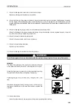
TOWING PIN
3
1.
Align protrusion (1) in the towing pin with groove (2) in the
counterweight, then insert the pin and turn it 180°.
2.
To prevent the towing pin from turning, fold the handle of
the towing pin and set it in position.
Reverse this operation to remove the pin.
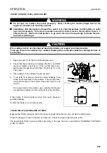
GREASE PUMP
3
The grease pump is stowed inside the left engine side cover at
the rear of the machine.
After using the pump, wipe off all the grease stuck to the pump,
set it in the clamp inside the cover, then fit the chain to the
clamp to prevent the pump from moving.
In addition, form the rubber ring into a figure of 8 as shown in
the diagram on the right, and secure in position.
CAB DOOR INNER LOCK
3
(Right door)
Press cab door inner lock to lock the door.
Position (a): Lock
Position (b): Release
Содержание WA320-5H
Страница 2: ...FOREWORD 11...
Страница 17: ...CONTENTS FOREWORD 1 16...
Страница 23: ...CE CONFORMING EQUIPMENT FOREWORD 1 22...
Страница 24: ...SAFETY 12...
Страница 25: ...SAFETY 2 2...
Страница 60: ...OPERATION 13...
Страница 181: ...TROUBLESHOOTING OPERATION 3 122...
Страница 182: ...MAINTENANCE 14...
Страница 243: ...SERVICE PROCEDURE MAINTENANCE 4 62...
Страница 244: ...TECHNICAL DATA 15...
Страница 246: ...TECHNICAL DATA TECHNICAL DATA 5 3...
Страница 248: ...ATTACHMENTS OPTIONS 16...
Страница 313: ...CENTRAL LUBRICATION SYSTEM ATTACHMENTS OPTIONS 6 66...
Страница 314: ...INDEX 17...
Страница 315: ...INDEX 7 2...
Страница 318: ...NOTES 18...
Страница 319: ...NOTES NOTES 8 2 NOTES 8...
Страница 320: ...NOTES NOTES 8 3...
Страница 321: ...2003 Komatsu Hanomag GmbH All Rights Reserved Printed in Europe 10 2003...


