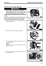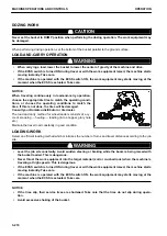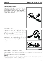
TRANSMISSION CUT-OFF FUNCTION
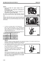
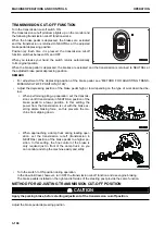
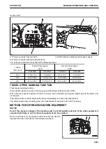
Turn the transmission cut-off switch ON.
The transmission cut-off pilot lamp lights up on the monitor and
the following transmission cut-off function works.
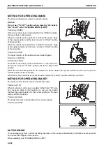
When the brake pedal is depressed, the brakes are actuated
and the transmission is returned to NEUTRAL at the adjusted
brake pedal depressing position.
Position (a): Each time it is pressed, the transmission cut-off
function switches between ON and OFF.
When you release your hand, the switch returns automatically
to its original position.
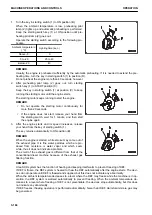
When the brake pedal is depressed, the brakes are actuated and the transmission is returned to NEUTRAL at
the adjusted brake pedal depressing position.
REMARK
• For adjustment of the depressing position of the brake pedal, see “METHOD FOR ADJUSTING TRANS-
MISSION CUT-OFF POSITION (3-196)”.
• Adjust the depressing position of the brake pedal high or low depending on the type of work described be-
low.
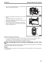
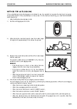
• When performing piling-up operation, set the transmis-
sion cut-off (transmission in NEUTRAL) position of the
brake pedal to a lower position. In this setting, the
power from the transmission is cut with the brake ex-
erting ample braking force, so this prevents the ma-
chine from slipping down.
• When approaching a dump truck during loading oper-
ation, set the transmission cut-off (transmission in
NEUTRAL) position of the brake pedal to a higher po-
sition. In this setting, the fine control of the brake is
only required just in front of the dump truck, so you
can control and stop the machine easily and softly.
• Turn the switch to ON position during operation.
In the downhill travel, however, turn OFF the transmission cut-off function and use engine braking.
The brake pedals installed on the right and left sides of the steering post provide the same function.
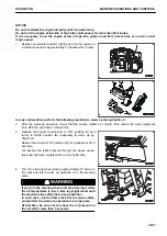
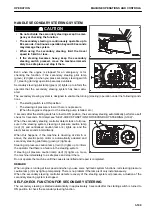
METHOD FOR ADJUSTING TRANSMISSION CUT-OFF POSITION
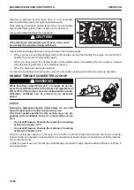
k
k
CAUTION
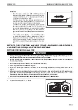
Apply the parking brake, before starting adjustment of the transmission cut-off position.
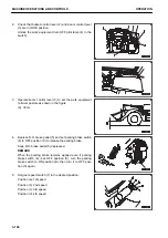
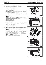
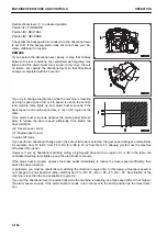
Adjust the brake pedal depressing position.
MACHINE OPERATIONS AND CONTROLS
OPERATION
3-196
Содержание WA480-8
Страница 2: ......
Страница 19: ...Distributor name Address Phone Fax Service personnel FOREWORD PRODUCT INFORMATION 1 17...
Страница 29: ...LOCATION OF SAFETY LABELS SAFETY SAFETY LABELS 2 3...
Страница 69: ...OPERATION Please read and make sure that you understand the SAFETY section before reading this section 3 1...
Страница 76: ...Outside of cab 1 Slow blow fuse 2 Dust indicator 3 Articulation lock pin 4 Toolbox GENERAL VIEW OPERATION 3 8...
Страница 159: ...SWITCHES 1 ECSS switch 2 Front working lamp switch OPERATION EXPLANATION OF COMPONENTS 3 91...
Страница 302: ...Securing position Fixing angle A 61 B 53 C 33 D 38 TRANSPORTATION OPERATION 3 234...
Страница 324: ......
Страница 325: ...MAINTENANCE Please read and make sure that you understand the SAFETY section before reading this section 4 1...
Страница 397: ...Viewed from the rear side of the machine MAINTENANCE MAINTENANCE PROCEDURE 4 73...
Страница 402: ......
Страница 403: ...SPECIFICATIONS 5 1...
Страница 405: ...1 Value when bucket dump angle is 45 B I A G E H F D C 9 J W0 1 4 5 6 SPECIFICATIONS SPECIFICATIONS 5 3...
Страница 406: ......
Страница 422: ......
Страница 423: ...REPLACEMENT PARTS 7 1...
Страница 439: ......
Страница 440: ...WA480 8 WHEEL LOADER Form No VENAM51500 2018 KOMATSU All Rights Reserved Printed in Europe 07 2018...

