


Engine
92
Filter Element Replacement
The air filter draws fresh air from the right side of the coach. It
is visible when the engine compartment door is open.
Read “Air
Restriction Indicator” and the NOTICE above before replacing
the air filter element.
Filter Element Removal
1. Remove the nuts securing the bottom cover of the air
cleaner.
2. Remove the cover and slide out the old element. Wipe out
the inside of the container with a clean cloth.
Filter Element Installation
1. Inspect the gasket sealing surface inside the air cleaner. It
must be smooth, flat, and clean.
2. Check to insure that all inlet and outlet accessories are of
the correct size and are not plugged.
3. Insert the new filter element.
4. Replace the bottom cover and install the nuts removed in
Step 1, Removal. Tighten the nuts securely to 8 ft-lb (10.5
N-m) torque.
5. Reset the air restriction indicator by depressing the button on the top of the indicator. Verify that
the color in the window of the indicator is GREEN.
Air Cleaner Assembly Removal
1. Disconnect the air restriction indicator supply hose.
2. Loosen the clamp securing the air intake hose and disconnect the hose from the air cleaner as-
sembly.
3. Loosen the clamp securing the hump hose and disconnect the hump hose from the air cleaner as-
sembly.
4. Support the air cleaner assembly and remove the two nuts and two bolts from the mounting
bracket clamps.
5. Carefully lower the air cleaner assembly from the engine compartment.
Air Cleaner Assembly Installation
Reverse the removal procedure. When installing the air cleaner assembly, be sure that the unit is prop-
erly positioned in the mounting bracket clamps before installing and tightening the clamp bolts. Use care
when tightening the clamp bolts not to overtighten to the point where the body will be deformed.
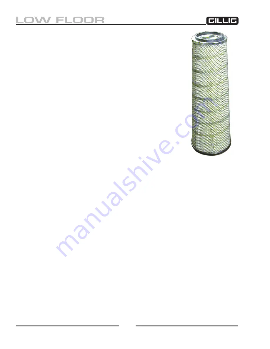
Figure 3-12, Air Filter Element
Содержание LOW FLOOR
Страница 18: ...Specifications 18...
Страница 58: ...Preventive Maintenance 58...
Страница 110: ...Engine 110...
Страница 138: ...Transmission Driveline Rear Axle 138...
Страница 182: ...Suspension 182...
Страница 260: ...Air System 260...
Страница 420: ...Electrical System 420 Deutsch DT Series Connectors...
Страница 421: ...Electrical System 421...
Страница 422: ...Electrical System 422 Deutsch HD 10 Series Connectors...
Страница 423: ...Electrical System 423...
Страница 424: ...Electrical System 424 Deutsch HD 30 Series Connectors...
Страница 425: ...Electrical System 425...
Страница 442: ...Heating Air Conditioning 442...
Страница 486: ...Body and Interior 486 Driver s Seat Troubleshooting Use the following chart to troubleshoot the USSC seat...
Страница 492: ...Body and Interior 492 Figure 11 33 USSC Seat Assembly...
Страница 493: ...Body and Interior 493 Figure 11 34 USSC Seat Suspension Assembly...
Страница 495: ...Body and Interior 495 Figure 11 37 Seat Air Connections...
Страница 506: ...GILLIG CORPORATION 25800 Clawiter Road Hayward CA 94545 Phone 510 785 1500 Fax 510 785 6819 Printed November 2006...


