


257
Air System
AIR SySTEM CONDENSER/SEPARATOR
Mounted between the air compressor and the air dryer, the Haldex
Consep air system condenser/separator condenses, separates, and
expels oil, water, and other contaminants before they can reach the
air dryer. This unit requires little maintenance. The drain valve’s
integrated filter prevents damage from large debris, while a built-in
heater prevents freeze up. The condenser/separator reduces corrosion
and possible failure of air brake system components caused by
contamination, and it significantly increases the air dryer’s desiccant
life.
Operation
Air enters the circular air path of the condenser/separator through its
side inlet port. Large external cooling fins cause oil, water, and other
contaminants to condense and separate from the air. Centrifugal effect
forces contaminants to the housing wall, where they run to the bottom
of the unit (the sump). Contaminants are held in the sump, while clean
air exits through the outlet port on top of the housing to continue on to
the remaining components of the air system. Contaminants are auto-
matically drained upon each brake application via the unit’s electroni-
cally controlled automatic drain valve.
Preventive Maintenance
The air system condenser/separator must be inspected periodically for proper operation. The interval
between inspections is determined by the type of service. High compressor duty cycles and high tem-
peratures can cause a buildup of carbon in the condenser, drain valve, and filter. This contamination must
be removed for proper operation. Inspection of the condenser/separator is recommended every 25,000
miles.
Inspection
1. Check connections at the unit for air leaks during the compressor loading cycle by applying a
soap solution around pipe fittings. Check the bottom of drain valve for air leaks around manual
drain port.
2. With ignition switch on and compressor pumping, apply brakes and release. After each brake
application and release, an audible click will be heard at the drain valve and a slight puff of air
will be expelled. If the valve does not operate, check electrical wiring for correct voltage (brakes
applied). Insure that the voltage matches the voltage given on the drain valve label. If there is no
current, check the electrical circuit at the unit’s relay and at the brake light switch. If the electri-
cal circuit is OK and the valve does not discharge, the unit must be serviced.
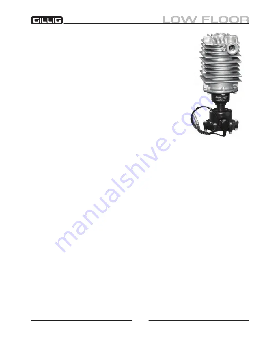
Figure 6-48, Haldex Consep
Condenser/Separator
Содержание LOW FLOOR
Страница 18: ...Specifications 18...
Страница 58: ...Preventive Maintenance 58...
Страница 110: ...Engine 110...
Страница 138: ...Transmission Driveline Rear Axle 138...
Страница 182: ...Suspension 182...
Страница 260: ...Air System 260...
Страница 420: ...Electrical System 420 Deutsch DT Series Connectors...
Страница 421: ...Electrical System 421...
Страница 422: ...Electrical System 422 Deutsch HD 10 Series Connectors...
Страница 423: ...Electrical System 423...
Страница 424: ...Electrical System 424 Deutsch HD 30 Series Connectors...
Страница 425: ...Electrical System 425...
Страница 442: ...Heating Air Conditioning 442...
Страница 486: ...Body and Interior 486 Driver s Seat Troubleshooting Use the following chart to troubleshoot the USSC seat...
Страница 492: ...Body and Interior 492 Figure 11 33 USSC Seat Assembly...
Страница 493: ...Body and Interior 493 Figure 11 34 USSC Seat Suspension Assembly...
Страница 495: ...Body and Interior 495 Figure 11 37 Seat Air Connections...
Страница 506: ...GILLIG CORPORATION 25800 Clawiter Road Hayward CA 94545 Phone 510 785 1500 Fax 510 785 6819 Printed November 2006...


