408
Electrical System
Extinguishable Ballast Replacement
Extinguishing ballast is used in combination with HO (high output) lamp tubes to extend the operational
life of lamp tubes required to switch with the doors. HO lamp tubes are bi-pin rather than single pin. The
bi-pin configuration is used in order to provide a limited but constant amount of power to the lamp tube
filaments, keeping them warm and ready for full power when required.
The installation of an HO lamp tube into a HO socket must be done with care by properly aligning the
lamp end with the socket. It is important when installing lamp tubes to inspect both the lamp ends for
damage and the lamp sockets for debris or bent contact pins before installation. Always insert the lamp
tube in the floating (push-spring) socket first and then the fixed socket. Never force or twist an HO lamp
tube into the socket as these actions may crack the recessed double contact (RDC) bays on the ends of
the lamp tubes.
The molded plastic comprising the RDC is very brittle. The RDC not only protects the pins from dam-
age, but most importantly keeps the lamp ends seated properly in the socket. An HO lamp tube with a
cracked RDC should not be used as the lamp will easily turn in the fixture, causing intermittent or no
contact with the lamp pins and socket receptacles.
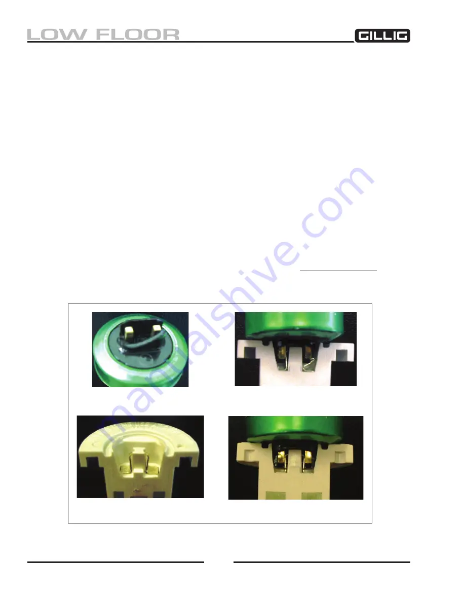
Broken pieces of the HO lamps RDC can become lodged in the HO socket. Any pieces of broken RDC
should be completely removed from the socket before installation of a new HO lamp tube. Inserting a
new HO lamp in an HO socket with RDC debris left in the socket can damage a new lamp tube’s RDC
and HO socket receptacle pins, causing a poor or non-existent connection.
Never force or twist HO
lamp tubes into their mating sockets, and always inspect both the lamps ends and socket before
installation.
Damaged RDC
Damaged RDC & Damaged
Socket Receptacle
High-Output Socket Receptacle
in Proper Condition
Cutaway RDC Shows
Proper Pin Contact
Figure 9-51, High-Output Lamp Tube and Socket Conditions
Содержание LOW FLOOR
Страница 18: ...Specifications 18...
Страница 58: ...Preventive Maintenance 58...
Страница 110: ...Engine 110...
Страница 138: ...Transmission Driveline Rear Axle 138...
Страница 182: ...Suspension 182...
Страница 260: ...Air System 260...
Страница 420: ...Electrical System 420 Deutsch DT Series Connectors...
Страница 421: ...Electrical System 421...
Страница 422: ...Electrical System 422 Deutsch HD 10 Series Connectors...
Страница 423: ...Electrical System 423...
Страница 424: ...Electrical System 424 Deutsch HD 30 Series Connectors...
Страница 425: ...Electrical System 425...
Страница 442: ...Heating Air Conditioning 442...
Страница 486: ...Body and Interior 486 Driver s Seat Troubleshooting Use the following chart to troubleshoot the USSC seat...
Страница 492: ...Body and Interior 492 Figure 11 33 USSC Seat Assembly...
Страница 493: ...Body and Interior 493 Figure 11 34 USSC Seat Suspension Assembly...
Страница 495: ...Body and Interior 495 Figure 11 37 Seat Air Connections...
Страница 506: ...GILLIG CORPORATION 25800 Clawiter Road Hayward CA 94545 Phone 510 785 1500 Fax 510 785 6819 Printed November 2006...


