24
Air System
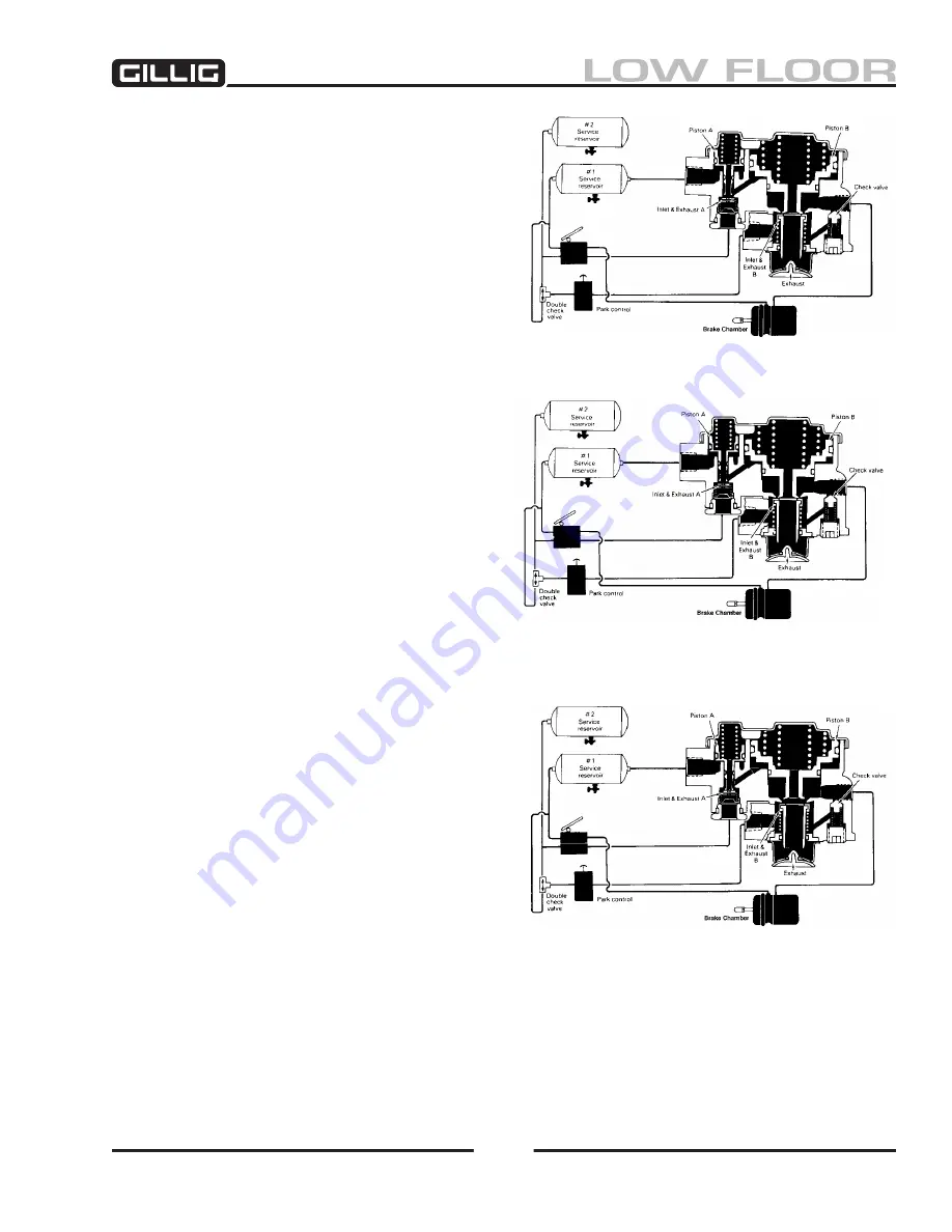
Figure 6-40, Normal Service Operation
Figure 6-41, Service Application (Loss of
Secondary Air Tank Pressure)
Figure 6-42, Service Application (Loss of
Primary Air Tank Pressure)
is made by actuating the E-8 brake valve, air from
the #2 delivery circuit is sent from the E-8 to SR-1’s
control port and is stopped at the closed inlet of valve
A. No movement of the SR-1’s internal components
takes place. Air from the E-8’s #1 delivery circuit
actuates the service section of the spring brake actua-
tors.
brake Application- loss of secondary tank
See Figure 6-41
. If the secondary air tank loses pres-
sure, the primary tank as well as the parking control
valve (PP-1) will be protected by the double and
single check valves in the air system. A service ap-
plication of the dual air brake valve in this situation
results in little or no air being delivered from the #2
delivery circuit to the control port of the SR-1. No
movement of the SR-1’s internal components will
take place. Braking is assured because the primary
air tank is protected by a check valve and the #1 de-
livery circuit of the E-8 brake valve will apply the
service section of the spring brake actuators.
brake Application- loss of primary tank
Refer to Figure 6-
42
. If air pressure in the primary
air tank falls below about 55 psi, the pressure
beneath piston A is insufficient to resist the spring
force above and piston A moves into contact with
valve A. Initial contact between piston A and valve
A closes the hollow exhaust passage of piston A.
Continued movement of the piston opens the inlet of
valve A.
The secondary air tank and the park control valve
(PP-1) are protected from pressure loss by the action
of the double check valve.
When a service application of the E-8 brake valve is
made, air delivered from the #2 delivery circuit of
the dual brake valve enters the SR-1 control port. Air
entering the control port moves past the inlet of valve
a and travels through a passage in the body to the un-
derside of piston B. Piston B moves up, opening the
exhaust of valve B. When the exhaust of valve B opens, air pressure trapped in the emergency section of
the spring brake actuator is allowed to escape, resulting in a brake application by the emergency section.
The amount of air pressure released from the spring brake is in proportion to the amount of air pressure
delivered to the control port of the SR-1 by the #2 delivery of the dual brake valve.
Содержание LOW FLOOR
Страница 18: ...Specifications 18...
Страница 58: ...Preventive Maintenance 58...
Страница 110: ...Engine 110...
Страница 138: ...Transmission Driveline Rear Axle 138...
Страница 182: ...Suspension 182...
Страница 260: ...Air System 260...
Страница 420: ...Electrical System 420 Deutsch DT Series Connectors...
Страница 421: ...Electrical System 421...
Страница 422: ...Electrical System 422 Deutsch HD 10 Series Connectors...
Страница 423: ...Electrical System 423...
Страница 424: ...Electrical System 424 Deutsch HD 30 Series Connectors...
Страница 425: ...Electrical System 425...
Страница 442: ...Heating Air Conditioning 442...
Страница 486: ...Body and Interior 486 Driver s Seat Troubleshooting Use the following chart to troubleshoot the USSC seat...
Страница 492: ...Body and Interior 492 Figure 11 33 USSC Seat Assembly...
Страница 493: ...Body and Interior 493 Figure 11 34 USSC Seat Suspension Assembly...
Страница 495: ...Body and Interior 495 Figure 11 37 Seat Air Connections...
Страница 506: ...GILLIG CORPORATION 25800 Clawiter Road Hayward CA 94545 Phone 510 785 1500 Fax 510 785 6819 Printed November 2006...


