Electrical System
374
Starter Motor
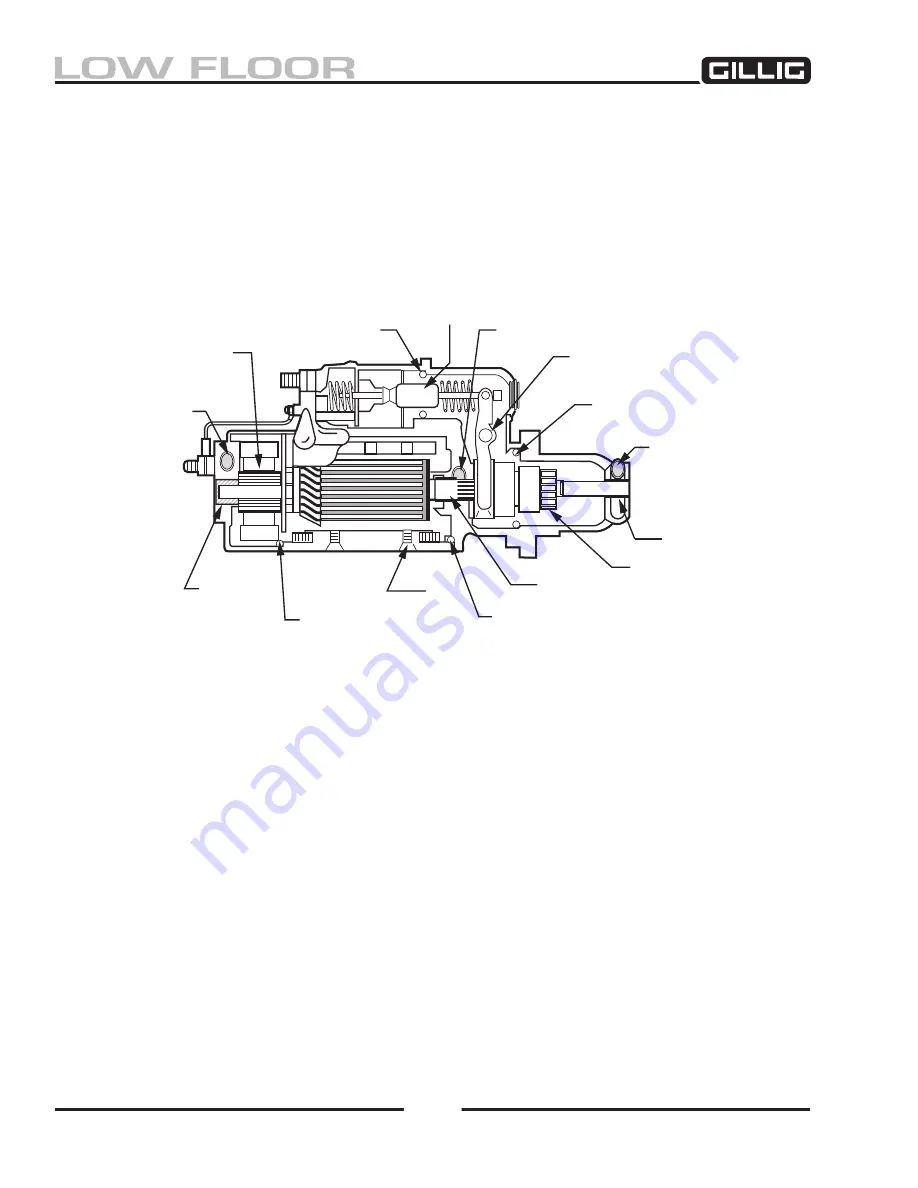
The electrical starter motor (Figure 9-16) is a heavy duty, solenoid operated unit.
The armature shaft is supported in sintered bronze bushings in three places: the commutator end frame,
the shift lever housing, and the nose housing.
O-ring seals are used between the commutator end frame and the field frame and between the shift lever
housing and the field frame. A spring-loaded lip-type oil seal, together with an O-ring seal in the shift
lever housing and a boot over the solenoid plunger prevent entry of oil into the armature, field coils, and
the solenoid case.
Starter Drive Operation
When the starter circuit is energized, the solenoid operates the shift lever to move the pinion into mesh
with the flywheel ring gear. At the end of the solenoid travel, the solenoid makes electrical contact to
complete the circuit for the starter motor. The motor then cranks the engine. The pinion remains engaged
until the starter solenoid circuit is interrupted. If the pinion fails to engage the ring gear, the motor will
not be energized, thus preventing damage to the pinion and gear teeth.
When the engine starts, the pinion overrunning clutch protects the armature from excessive speed until
the switch is opened, at which time the return spring causes the pinion to disengage.
If a tooth abutment occurs, the pinion is indexed without the motor rotating. This is accomplished by
shifting the drive down the armature straight splines until the pinion contacts the right gear. The drive
has an internal spiral spline and, as the solenoid continues to push the drive toward the ring gear, the
internal spline rotates the pinion off the tooth abutment. As the pinion is indexed, the internal drive
meshing spring is compressed, which forces the drive into the ring gear. The drive then moves forward,
permitting the solenoid contact disk to close against the terminals and allow the motor to turn.
Figure 9-16, Starter Motor
WICK
BRUSH
O-RING
WICK
SOLENOID
SHIFT LEVER
O-RING
WICK
BEARING
BEARING
PINION
O-RING
SEAL
O-RING
BEARING
20-800-53
Содержание LOW FLOOR
Страница 18: ...Specifications 18...
Страница 58: ...Preventive Maintenance 58...
Страница 110: ...Engine 110...
Страница 138: ...Transmission Driveline Rear Axle 138...
Страница 182: ...Suspension 182...
Страница 260: ...Air System 260...
Страница 420: ...Electrical System 420 Deutsch DT Series Connectors...
Страница 421: ...Electrical System 421...
Страница 422: ...Electrical System 422 Deutsch HD 10 Series Connectors...
Страница 423: ...Electrical System 423...
Страница 424: ...Electrical System 424 Deutsch HD 30 Series Connectors...
Страница 425: ...Electrical System 425...
Страница 442: ...Heating Air Conditioning 442...
Страница 486: ...Body and Interior 486 Driver s Seat Troubleshooting Use the following chart to troubleshoot the USSC seat...
Страница 492: ...Body and Interior 492 Figure 11 33 USSC Seat Assembly...
Страница 493: ...Body and Interior 493 Figure 11 34 USSC Seat Suspension Assembly...
Страница 495: ...Body and Interior 495 Figure 11 37 Seat Air Connections...
Страница 506: ...GILLIG CORPORATION 25800 Clawiter Road Hayward CA 94545 Phone 510 785 1500 Fax 510 785 6819 Printed November 2006...


