


Engine
89
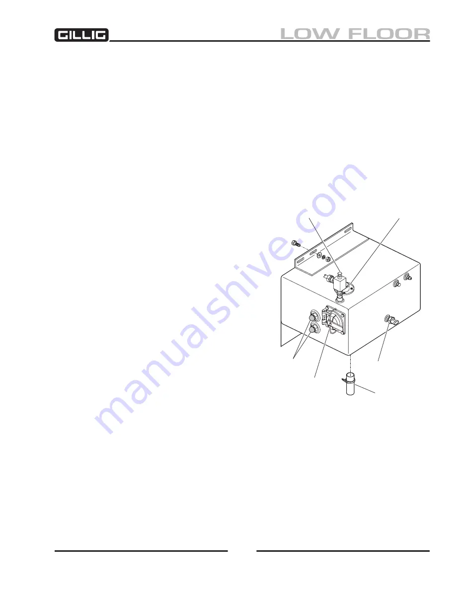
SURGE TANK
The surge tank (Figure 3-10) is mounted separately from the radiator in the left rear corner of the engine
compartment. It is equipped with a fill cap, an automatic pressure relief valve, a manual pressure relief
valve, an overflow tube, two sight glasses, and a low coolant indicator probe.
The automatic pressure relief valve performs two functions: relief of excessive pressure, and addition of
air when the coolant contracts when the engine stops running.
The manual pressure relief valve allows for manual relief of system pressure to perform maintenance or
system inspections.
Each of the two sight glasses consists of a screw-in lens, a seal, and a lens base. The lens is removed by
turning the glass in a counterclockwise direction. Use a new O-ring when installing a new sight glass.
Be careful not to damage the threads on the edge of the glass.
Surge Tank Removal
1. Relieve system pressure using the manual
pressure relief valve.
2. Drain the cooling system to a level below the
level of the surge tank.
3. Detach and tag all lines to the tank, including
the electrical line to the low coolant indicator
probe, if installed.
4. Remove the mounting bolts, washers, and
nuts that attach the tank to the side framing.
Remove the tank from the coach through the
rear engine door.
5. Replace or repair parts or components
as necessary.
Surge Tank Installation
1. Ensure that the tank is free from debris or
contaminants.
2. Install the bolts, washers, and nuts to secure
the tank to the side framing. Tighten the bolts
to 25–35 ft-lb
(35–45 N-m) torque.
3. Connect all lines and electrical leads.
4. Top up the system as prescribed in “Coolant
Fill Procedure” in this chapter.
Figure 3-10, Surge Tank
Auto Pressure
Relief Valve
Manual Pressure
Relief Valve
Sight Glasses
Fill Cap
Low Coolant
Indicator Probe
Overflow Tube
Содержание LOW FLOOR
Страница 18: ...Specifications 18...
Страница 58: ...Preventive Maintenance 58...
Страница 110: ...Engine 110...
Страница 138: ...Transmission Driveline Rear Axle 138...
Страница 182: ...Suspension 182...
Страница 260: ...Air System 260...
Страница 420: ...Electrical System 420 Deutsch DT Series Connectors...
Страница 421: ...Electrical System 421...
Страница 422: ...Electrical System 422 Deutsch HD 10 Series Connectors...
Страница 423: ...Electrical System 423...
Страница 424: ...Electrical System 424 Deutsch HD 30 Series Connectors...
Страница 425: ...Electrical System 425...
Страница 442: ...Heating Air Conditioning 442...
Страница 486: ...Body and Interior 486 Driver s Seat Troubleshooting Use the following chart to troubleshoot the USSC seat...
Страница 492: ...Body and Interior 492 Figure 11 33 USSC Seat Assembly...
Страница 493: ...Body and Interior 493 Figure 11 34 USSC Seat Suspension Assembly...
Страница 495: ...Body and Interior 495 Figure 11 37 Seat Air Connections...
Страница 506: ...GILLIG CORPORATION 25800 Clawiter Road Hayward CA 94545 Phone 510 785 1500 Fax 510 785 6819 Printed November 2006...


