245
Air System
2
9
4
3
7
8
6
5
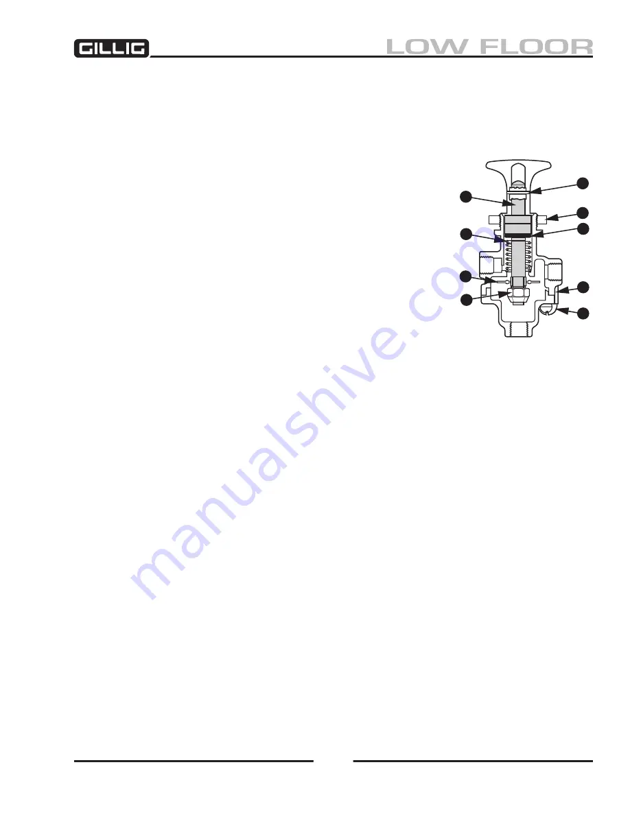
Figure 6-44, PP-1 Components
Parking Brake Control Valve (Bendix PP-)
The parking brake control valve is a Bendix PP-1 manually operable on-off air control valve with an ex-
haust function. Refer to the “Spring Brake Valve- Bendix SR-1" section of this chapter for a description
of parking brake air system operation.
PP- Preventive Maintenance
Every 50,000 miles, 6 months, or 1,800 operating hours, rebuild the
PP-1.
PP- Removal
Block and/or hold the vehicle by a means other than air brakes and
drain all air tanks to zero psi. Callouts refer to the numbers in Figure
6-
44
,
1. Drive the button roll-pin (1) out with a punch and remove the
button.
2. Unplumb the air connections, remove the panel mounting nut
(2), and remove the valve.
PP- Installation
1. Install valve in panel, securing with the panel mounting nut.
2. Reconnect the air lines.
3. Install the operating button. Secure with the roll pin (1).
PP- Disassembly
1. Remove the two capscrews (3) which retain the lower cover and remove the cover. Remove the
sealing ring (4).
2. Insert a small punch through the roll pin hole in the stem and remove the locknut (5) with a 7/16"
wrench.
3. Remove inlet/exhaust valve (6), plunger (7) and spring (8) (if any).
4. Remove O-ring (9) from plunger.
PP- Operating and Leakage Test
1. Connect a 120 psi air source to the supply port. An accurate test gauge should be tee’d into the
supply line and a means of controlling the supply pressure provided. A small volume with a
gauge should be connected to the delivery port.
2. With 120 psi supply pressure, the knob pulled up (exhaust position), leakage at the exhaust port
or the plunger stem should not exceed a 1" soap bubble in 5 seconds. There should be no leakage
between the upper and lower body.
3. Push the knob in (applied position). Leakage at the exhaust port or the plunger should not exceed
a 1" bubble in 3 seconds.
4. Reduce the supply pressure. At a pressure of 40 psi, the button should pop up automatically.
Содержание LOW FLOOR
Страница 18: ...Specifications 18...
Страница 58: ...Preventive Maintenance 58...
Страница 110: ...Engine 110...
Страница 138: ...Transmission Driveline Rear Axle 138...
Страница 182: ...Suspension 182...
Страница 260: ...Air System 260...
Страница 420: ...Electrical System 420 Deutsch DT Series Connectors...
Страница 421: ...Electrical System 421...
Страница 422: ...Electrical System 422 Deutsch HD 10 Series Connectors...
Страница 423: ...Electrical System 423...
Страница 424: ...Electrical System 424 Deutsch HD 30 Series Connectors...
Страница 425: ...Electrical System 425...
Страница 442: ...Heating Air Conditioning 442...
Страница 486: ...Body and Interior 486 Driver s Seat Troubleshooting Use the following chart to troubleshoot the USSC seat...
Страница 492: ...Body and Interior 492 Figure 11 33 USSC Seat Assembly...
Страница 493: ...Body and Interior 493 Figure 11 34 USSC Seat Suspension Assembly...
Страница 495: ...Body and Interior 495 Figure 11 37 Seat Air Connections...
Страница 506: ...GILLIG CORPORATION 25800 Clawiter Road Hayward CA 94545 Phone 510 785 1500 Fax 510 785 6819 Printed November 2006...


