Air System
247
AIR DRyER (BENDIx AD-9)
The function of the air dryer is to collect and remove air system contaminants in solid, liquid, and vapor
form before they enter the brake system. The air dryer provides clean, dry air to the components of the
brake and accessory systems. This increases the life of the system and reduces maintenance costs.
Regular Scheduled Maintenance
If moisture is present, the desiccant cartridge may require replacement. The following conditions can
also cause water accumulation and should be considered and corrected before replacing the desiccant.
• An outside air source has been used to charge the system, such as a tow vehicle or the shop air
system, and the air did not pass through the air dryer.
• Air usage is exceptionally high and not normal. This may be due to excessive accessory air de-
mands or leakage. Unusually high air requirements that do not allow the compressor to load and
unload (compressing and non-compressing cycle) in a normal fashion can cause moisture accumu-
lation. Check for high air system leakage.
• In areas where more than a 30° range of temperature fluctuation occurs in one day, small amounts
of water can accumulate in the air brake system due to condensation. Under these conditions, the
presence of small amounts of water should not be an indication that the dryer is not performing
properly.
Note also that a small amount of oil in the system may be nor-
mal and should not, in itself, be considered a reason to replace
the desiccant. An oil stained desiccant can function adequately.
1. Check the mounting bolts for tightness. Tighten to 25
ft-lb (35 N-m) torque.
2. Check the operation of the check valve in the end cover
of the air dryer. Build the air system pressure to gov-
ernor cut-out and observe a test gauge installed in the
wet tank. A rapid loss of pressure could indicate a failed
check valve. This can be confirmed by checking at
the purge valve exhaust. The purge valve will be open
when the governor cut-out pressure is reached. Allow
two minutes for completion of the purge cycle before
testing the check valve.
3. Check for excessive leakage at the purge valve by coat-
ing the exhaust with a soap solution while the compres-
sor is loaded (compressing air).
4. Check the operation of the safety valve by pulling the
exposed stem while the compressor is loaded (com-
pressing air). There must be an exhaust of air while the
stem is held and the valve should reseat when the stem
is released.
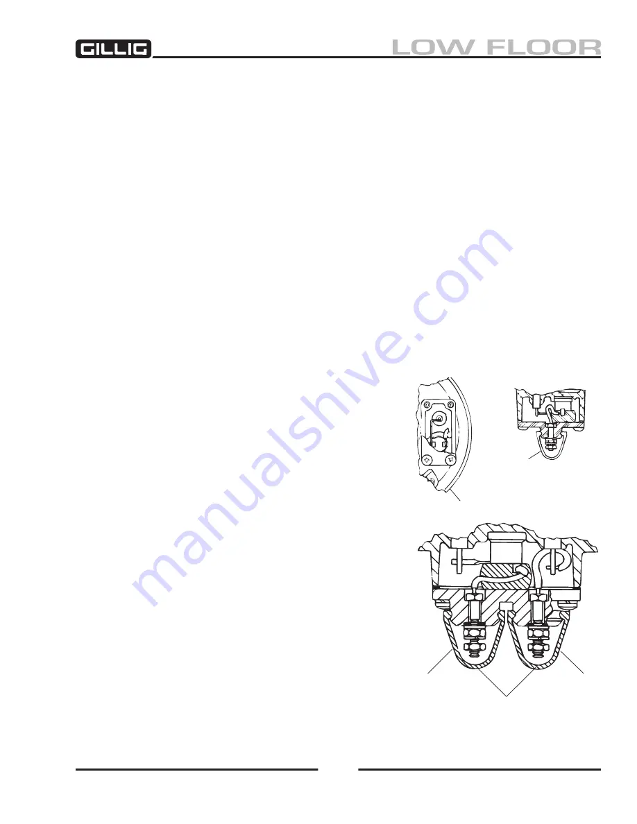
Figure 6-46, Thermostat Assembly
Boot
Boot
Connection for Power
and Insulated Return
Heater Post
Thermostat
Cover
Содержание LOW FLOOR
Страница 18: ...Specifications 18...
Страница 58: ...Preventive Maintenance 58...
Страница 110: ...Engine 110...
Страница 138: ...Transmission Driveline Rear Axle 138...
Страница 182: ...Suspension 182...
Страница 260: ...Air System 260...
Страница 420: ...Electrical System 420 Deutsch DT Series Connectors...
Страница 421: ...Electrical System 421...
Страница 422: ...Electrical System 422 Deutsch HD 10 Series Connectors...
Страница 423: ...Electrical System 423...
Страница 424: ...Electrical System 424 Deutsch HD 30 Series Connectors...
Страница 425: ...Electrical System 425...
Страница 442: ...Heating Air Conditioning 442...
Страница 486: ...Body and Interior 486 Driver s Seat Troubleshooting Use the following chart to troubleshoot the USSC seat...
Страница 492: ...Body and Interior 492 Figure 11 33 USSC Seat Assembly...
Страница 493: ...Body and Interior 493 Figure 11 34 USSC Seat Suspension Assembly...
Страница 495: ...Body and Interior 495 Figure 11 37 Seat Air Connections...
Страница 506: ...GILLIG CORPORATION 25800 Clawiter Road Hayward CA 94545 Phone 510 785 1500 Fax 510 785 6819 Printed November 2006...


