Hydraulic System
30
ALLEN
SCREW
CAP
CAP
SUPPLY
PORT
PILOT
RETURN
UNION
BONDED
WASHER
SHIMS
SPRING
POPPET
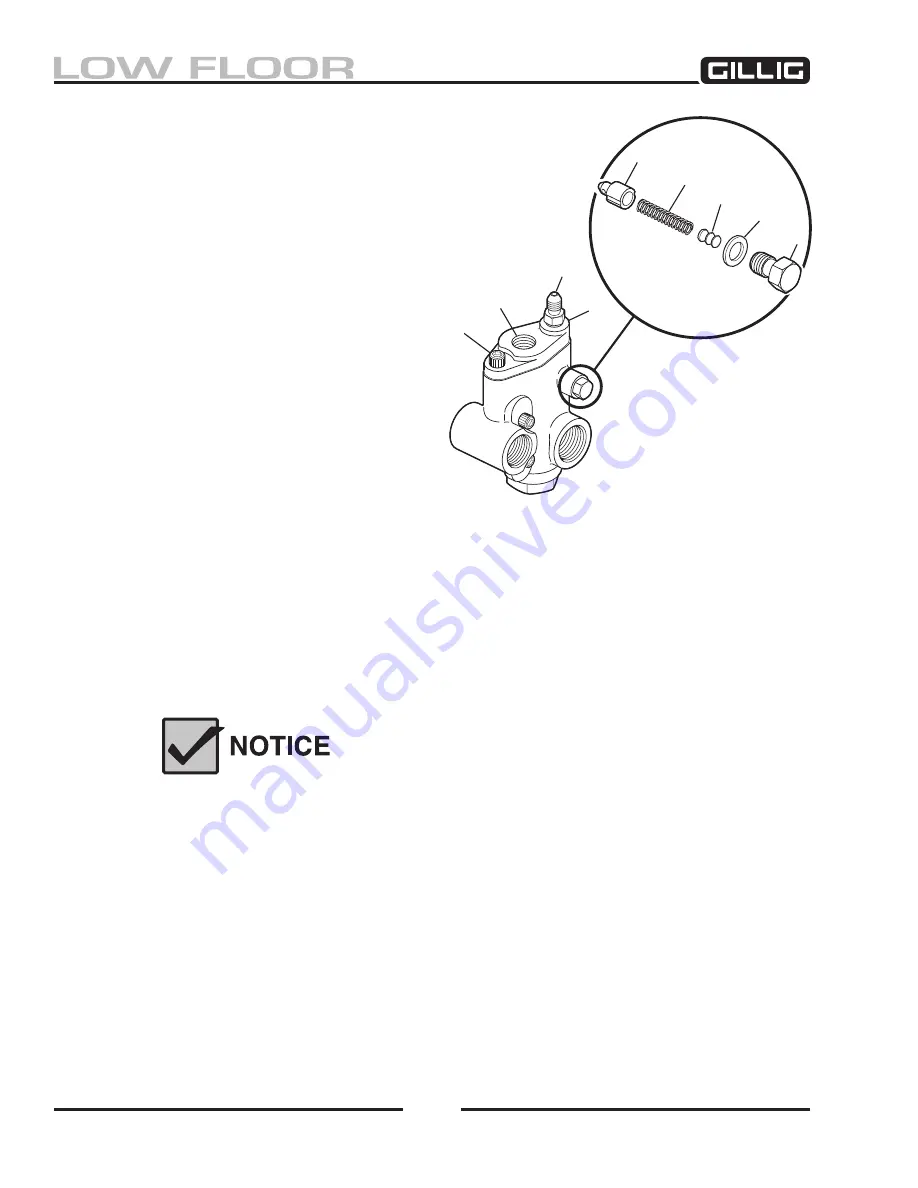
RELIEF VALVE
Figure 8-4, Switch Valve Relief Valve
Troubleshooting the Fan Motor Circuit
Fan Does Not Run When the Engine Reaches High
Temperature.
To determine whether the fan is failing to turn on due to de-
fective hydraulic components or due to a problem with the
fan control system, do the following to, in effect, remove
the control system from the fan motor circuit and
determine the source of the problem. For this pro-
cedure, the fan is said to be off or “idling” at fan
speeds of 0–500 RPM. The fan is said to be “on”
at fan speeds of 1,500–2,000 RPM, depending
upon the model of engine installed on your bus.
1. Run the engine at governed speed until the
fan cut-in temperature is reached (coolant
temperature should be at least 205°F).
2. Check the fan speed using a photo
tachometer. If the fan does not turn on (spin
1,500 RPM or more), do the following:
a. Stop the engine.
b. Disconnect the pilot line to the fan control valve.
c. Block the port in the fan control valve and the line to the control valve that was disconnected
in the step above.
Blocking the pilot lines to the fan control valve ensures that the switch valve (also known as
spool valve) forces pump flow to the fan motor. With maximum flow to the fan motor, the fan
should reach its maximum speed.
This procedure can be used to operate the bus in the event a problem
exists with the fan controller or in the engine electronics. It bypasses the
electronics system entirely and provides full cooling capabilities. This
procedure should only be used in an emergency situation.
3. Run the engine at governed speed. Check the fan speed using a photo tachometer.
If the fan DOES turn on (spin at 1,500 RPM or more), the likely cause of the problem is the fan
control system.
If this speed cannot be reached, the most likely causes are listed below in order of probability:
• Defective or malfunctioning fan motor switch valve (spool valve).
• Defective pressure relief valve at fan motor.
• Defective hydraulic pump.
• Defective fan motor—could be damaged or leaking excessively inside.
Содержание LOW FLOOR
Страница 18: ...Specifications 18...
Страница 58: ...Preventive Maintenance 58...
Страница 110: ...Engine 110...
Страница 138: ...Transmission Driveline Rear Axle 138...
Страница 182: ...Suspension 182...
Страница 260: ...Air System 260...
Страница 420: ...Electrical System 420 Deutsch DT Series Connectors...
Страница 421: ...Electrical System 421...
Страница 422: ...Electrical System 422 Deutsch HD 10 Series Connectors...
Страница 423: ...Electrical System 423...
Страница 424: ...Electrical System 424 Deutsch HD 30 Series Connectors...
Страница 425: ...Electrical System 425...
Страница 442: ...Heating Air Conditioning 442...
Страница 486: ...Body and Interior 486 Driver s Seat Troubleshooting Use the following chart to troubleshoot the USSC seat...
Страница 492: ...Body and Interior 492 Figure 11 33 USSC Seat Assembly...
Страница 493: ...Body and Interior 493 Figure 11 34 USSC Seat Suspension Assembly...
Страница 495: ...Body and Interior 495 Figure 11 37 Seat Air Connections...
Страница 506: ...GILLIG CORPORATION 25800 Clawiter Road Hayward CA 94545 Phone 510 785 1500 Fax 510 785 6819 Printed November 2006...


