


97
Air System
Compressor Removal and Installation
• To prevent serious eye injury, always wear safe eye protection when
you perform vehicle maintenance or service.
• Remove all pressure from the air system before you disconnect any
component. Pressurized air can cause serious personal injury.
• Block the wheels to prevent the vehicle from moving. Support the
vehicle with safety stands. Do not work under a vehicle supported
only by jacks. Jacks can slip and fall over. Serious personal injury
can result.
Compressor Removal
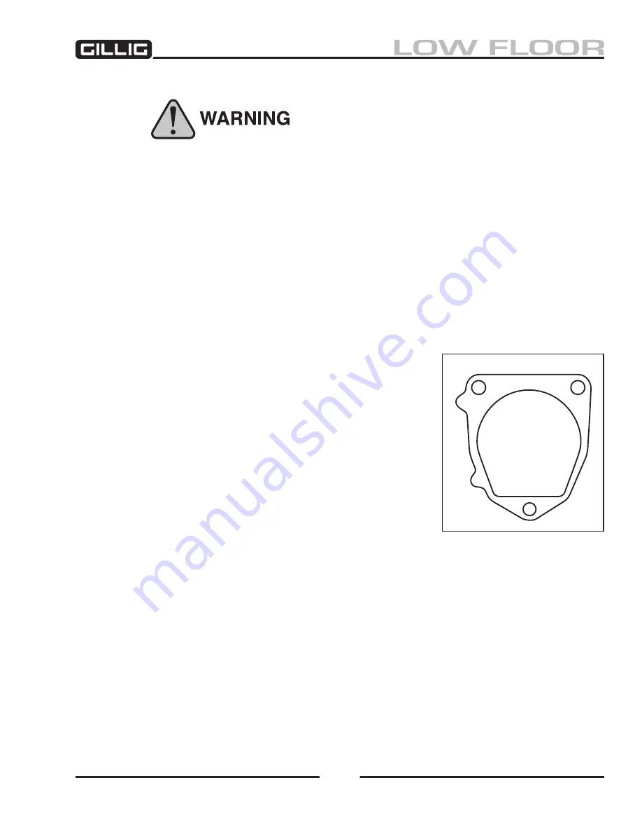
The front of the Cummins 18.7 air compressor is mounted to the engine. Before you remove the com-
pressor, make sure you have a replacement gasket to install with the new compressor. Call Cummins Inc.
for current part number. See Figure 6-
10.
The removal instructions given in this manual are general.
Depending on the configuration of your bus, additional steps
may be required.
1. Set the spring (parking) brakes and block the wheels of
the vehicle.
2. Drain the air pressure from the air system.
3. Drain the engine cooling system and the cylinder head of
the compressor.
4. Disconnect all air and water lines leading to the compres
-
sor.
5.
Through-drive version air compressor only:
If there is
a power steering pump installed at the back of the com-
pressor, remove the power steering pump. Disconnect the
power steering pump. It is not necessary to remove pumps installed at the front of the compres-
sor. See Figure 6-
11.
6. Remove the discharge and coolant fittings. Note fitting locations to aid in assembly.
7. Loosen the three flange mounting bolts that hold the compressor to the engine.
8. Remove the compressor from the vehicle.
Remove and retain the oil supply tube that runs
between the compressor and the engine. See Figure 6-12.
Figure 6-10, Replacement Gasket
Содержание LOW FLOOR
Страница 18: ...Specifications 18...
Страница 58: ...Preventive Maintenance 58...
Страница 110: ...Engine 110...
Страница 138: ...Transmission Driveline Rear Axle 138...
Страница 182: ...Suspension 182...
Страница 260: ...Air System 260...
Страница 420: ...Electrical System 420 Deutsch DT Series Connectors...
Страница 421: ...Electrical System 421...
Страница 422: ...Electrical System 422 Deutsch HD 10 Series Connectors...
Страница 423: ...Electrical System 423...
Страница 424: ...Electrical System 424 Deutsch HD 30 Series Connectors...
Страница 425: ...Electrical System 425...
Страница 442: ...Heating Air Conditioning 442...
Страница 486: ...Body and Interior 486 Driver s Seat Troubleshooting Use the following chart to troubleshoot the USSC seat...
Страница 492: ...Body and Interior 492 Figure 11 33 USSC Seat Assembly...
Страница 493: ...Body and Interior 493 Figure 11 34 USSC Seat Suspension Assembly...
Страница 495: ...Body and Interior 495 Figure 11 37 Seat Air Connections...
Страница 506: ...GILLIG CORPORATION 25800 Clawiter Road Hayward CA 94545 Phone 510 785 1500 Fax 510 785 6819 Printed November 2006...


