26
Air System
The circuits in the E-10R Retarder Control Brake Valves are identified as follows: The No. 1 or primary
circuit is that portion of the valve between the spring seat which contacts the plunger and the relay pis-
ton; the No. 2 or secondary circuit is that portion between the relay piston and the exhaust cavity.
The primary circuit of the valve is similar in operation to a standard single circuit air brake valve and
under normal operating conditions the secondary circuit is similar in operation to a relay valve.
Both primary and secondary circuits of the brake valve use a common exhaust protected by an exhaust
diaphragm.
Operation
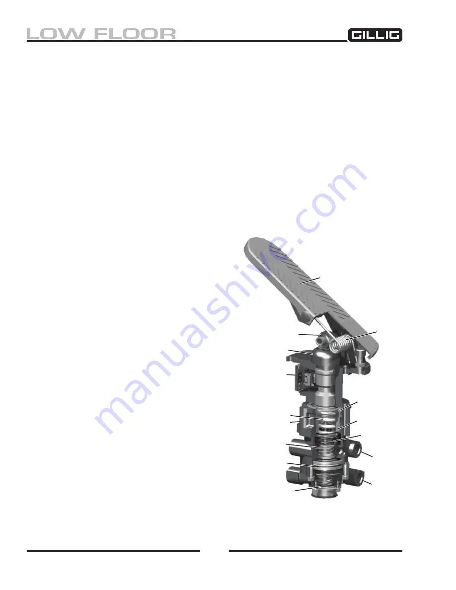
Refer to Figure 6-27.
Applying: Normal Operation – No. 1 or Primary Circuit Portion
When the brake treadle is depressed, the plunger exerts force on the spring seat (5), graduating spring
(12), and primary piston (11). The primary piston, which contains the exhaust valve seat, closes the
primary exhaust valve. As the exhaust valve closes, the
primary inlet valve is moved off its seat allowing prima-
ry air to flow out the No. 1 or primary delivery port.
Applying: Normal Operation - No. 2 or Secondary
circuit
When the primary inlet valve (29) is moved off its seat,
air is permitted to pass through the bleed passage and
enters the relay piston cavity. The air pressure moves the
relay piston (24), which contains the exhaust seat, and
closes the secondary exhaust valve. As the secondary
exhaust valve closes, the inlet valve (19) is moved off its
seat allowing the secondary air to flow out the delivery
of the same circuit. Because of the small volume of air
required to move the relay piston (24), action of the sec
-
ondary circuit of the valve is almost simultaneous with
the primary circuit portion.
Applying: Loss of Air in the No. 2 or Secondary
circuit
Should air be lost in the No. 2 or secondary circuit, the
No. 1 or primary circuit will continue to function as de-
scribed above under Normal Operation: No.1 or Primary
Circuit Portion.
Applying: Loss of Air in the No. 1 or Primary Cir
-
cuit
Should air be lost in the primary circuit, the function
will be as follows: As the brake treadle is depressed and
no air pressure is present in the primary circuit supply
Figure 6-27, Cross Section
5
2
30
20
Treadle
Spring
Roller
Boot
6
3
29
24
9
Содержание LOW FLOOR
Страница 18: ...Specifications 18...
Страница 58: ...Preventive Maintenance 58...
Страница 110: ...Engine 110...
Страница 138: ...Transmission Driveline Rear Axle 138...
Страница 182: ...Suspension 182...
Страница 260: ...Air System 260...
Страница 420: ...Electrical System 420 Deutsch DT Series Connectors...
Страница 421: ...Electrical System 421...
Страница 422: ...Electrical System 422 Deutsch HD 10 Series Connectors...
Страница 423: ...Electrical System 423...
Страница 424: ...Electrical System 424 Deutsch HD 30 Series Connectors...
Страница 425: ...Electrical System 425...
Страница 442: ...Heating Air Conditioning 442...
Страница 486: ...Body and Interior 486 Driver s Seat Troubleshooting Use the following chart to troubleshoot the USSC seat...
Страница 492: ...Body and Interior 492 Figure 11 33 USSC Seat Assembly...
Страница 493: ...Body and Interior 493 Figure 11 34 USSC Seat Suspension Assembly...
Страница 495: ...Body and Interior 495 Figure 11 37 Seat Air Connections...
Страница 506: ...GILLIG CORPORATION 25800 Clawiter Road Hayward CA 94545 Phone 510 785 1500 Fax 510 785 6819 Printed November 2006...


