Electrical System
47
WHEELCHAIR RAMP
The driver controls the ramp from the ramp controls located at the lower part of the RH dash panel. Re-
fer to the
Driver’s Handbook
for proper operating procedures.
The wheelchair ramp is a self-contained unit located in the entrance platform floor. The ramp is entirely
electrically operated. To perform repairs or adjustments to the ramp, refer to the Lift-U
Technical
Reference Manual
provided with the coach. To troubleshoot the coach circuits that provide power to
operate the ramp, see the
Schematics Manual
provided with the coach.
Incorrect operation of the passenger ramp can result in damage to the
bus or injury to passengers! Do not try to use the ramp until you have
read and understood all of the ramp instructions and safety warnings in
the
Driver’s Handbook
and in the Lift-U
Technical Reference Manual
.
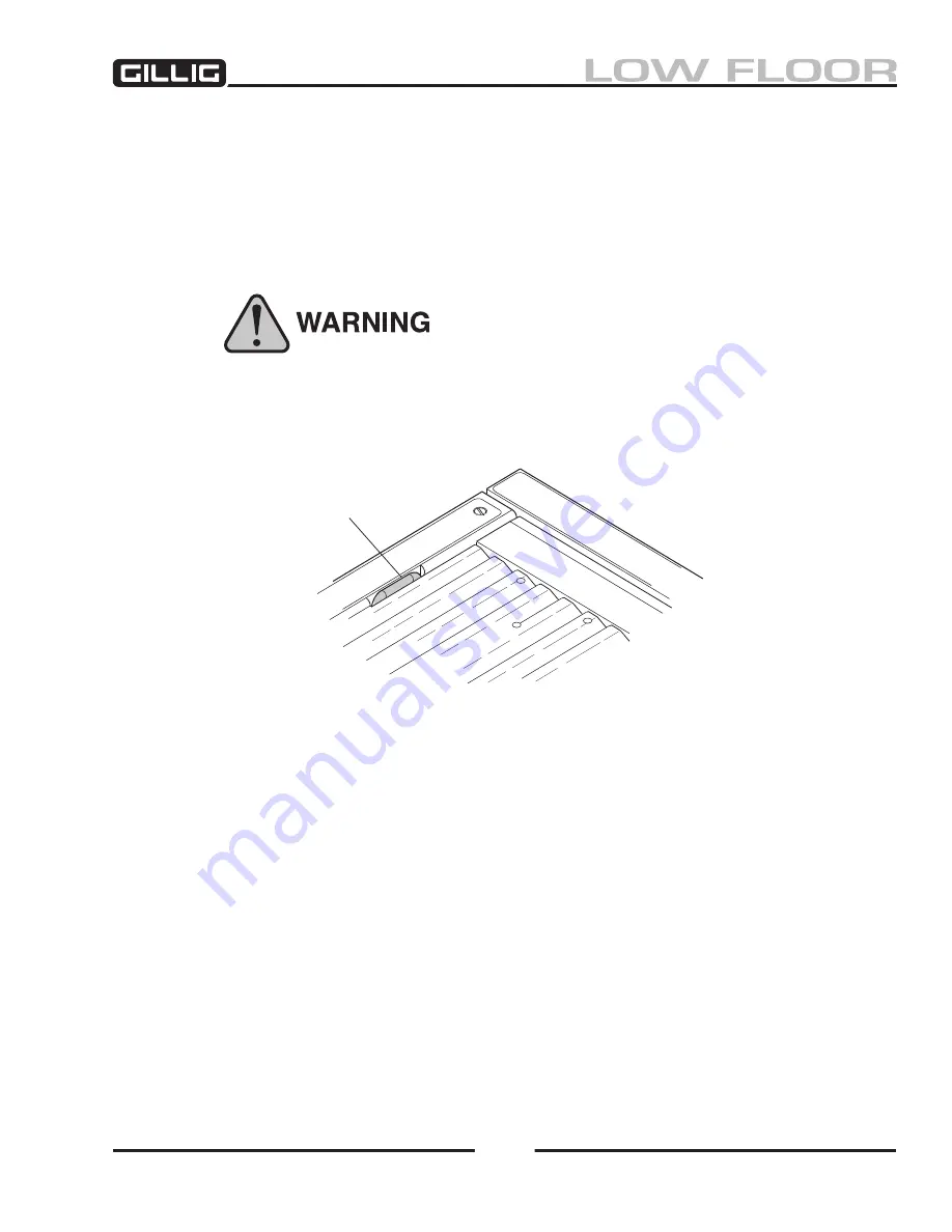
MANUAL LATCH
Figure 9-57, Manual Release Latch
Manual Deploy Procedure
If the ramp cannot be operated electrically, a manual latch release handle is provided to allow the opera-
tor to manually deploy and/or stow the ramp.
Once the release handle has been pulled to release the solenoid latch, the ramp is free to rotate to the
fully deployed position or to the fully stowed and latched position.
1. At all times during the manual deploy procedure, verify there is no person in the path of the ramp
as it is slowly extended to the fully deployed position.
2. Locate the manual release latch handle. See Figure 9-
57 above.
3. With your fingers, pull up on the release latch handle. The solenoid latch will release the ramp
platform from its latched state.
4. Lift the ramp up and slowly push the ramp out to approximately 30 degrees beyond the vertical
position. Using your foot, apply the minimum pressure required to continue the slow descent of
the ramp platform. When the outermost edge of the ramp comes to rest on the ground or side-
walk adjacent to the coach, forming a ramp, the ramp is then ready to load or unload passengers
as directed by the operator.
Содержание LOW FLOOR
Страница 18: ...Specifications 18...
Страница 58: ...Preventive Maintenance 58...
Страница 110: ...Engine 110...
Страница 138: ...Transmission Driveline Rear Axle 138...
Страница 182: ...Suspension 182...
Страница 260: ...Air System 260...
Страница 420: ...Electrical System 420 Deutsch DT Series Connectors...
Страница 421: ...Electrical System 421...
Страница 422: ...Electrical System 422 Deutsch HD 10 Series Connectors...
Страница 423: ...Electrical System 423...
Страница 424: ...Electrical System 424 Deutsch HD 30 Series Connectors...
Страница 425: ...Electrical System 425...
Страница 442: ...Heating Air Conditioning 442...
Страница 486: ...Body and Interior 486 Driver s Seat Troubleshooting Use the following chart to troubleshoot the USSC seat...
Страница 492: ...Body and Interior 492 Figure 11 33 USSC Seat Assembly...
Страница 493: ...Body and Interior 493 Figure 11 34 USSC Seat Suspension Assembly...
Страница 495: ...Body and Interior 495 Figure 11 37 Seat Air Connections...
Страница 506: ...GILLIG CORPORATION 25800 Clawiter Road Hayward CA 94545 Phone 510 785 1500 Fax 510 785 6819 Printed November 2006...


