


25
Air System
BRAKE SySTEM OPERATION
See Figure 6-1. The driver’s brake pedal controls the brake (foot) valve which directs primary reservoir
air to apply the rear brakes and secondary reservoir air to apply the front brakes. The spring brake (emer-
gency/parking) is pressurized to compress the spring (released position) by both primary and secondary
reservoir air to keep the spring brake disengaged.
A dual pointer air gauge, mounted in the driver’s dash, is connected to the two brake system reservoirs.
The red pointer indicates the pressure in the secondary tank and the green or white pointer indicates the
pressure in the primary tank.
If air pressure is lost in the secondary reservoir, the front brakes will be disabled but the rear brakes are
powerful enough to stop the bus. If air pressure is lost in the primary reservoir, the spring brake modula-
tor valve (SBM) will sense the front brake pressure and proportionally modulate the secondary air pres
-
sure to the spring brake actuator, allowing the spring brake to apply the rear brakes to aid in stopping the
bus. This will only work for a few brake applications until the secondary reservoir air supply is depleted.
BRAKE VALVES
Brake Valve (Bendix E-0R)
The E-10R Retarder Control Brake Valve is used
with retarder systems installed on automatic
transmissions. The retarder system is actuated
early in the brake application, before air pressure
is delivered. Refer to Figures 6-27 and 6-28 for
item numbers referenced in parenthesis.
The E-10R is capable of controlling up to a
three-stage retarder (different levels of retarda-
tion) through the sequencing of its three electrical
switches. The sequencing of these switches is
important to the proper operation of the retarder.
E-10R Retarder Control Brake Valve is a floor
mounted, treadle operated type brake valve with
two separate supply and delivery circuits for
service (primary and secondary) braking, which
provides the driver with a graduated control for
applying and releasing the vehicle brakes.
The E-10R uses a metal coil spring (6) housed in
an upper body assembly. The use of a metal coil
spring (and the upper body assembly) provides
greater treadle travel and, therefore, provides the
driver with a less sensitive “feel” when making a
brake application. This allows for smooth brake
application, which contributes to passenger com-
fort.
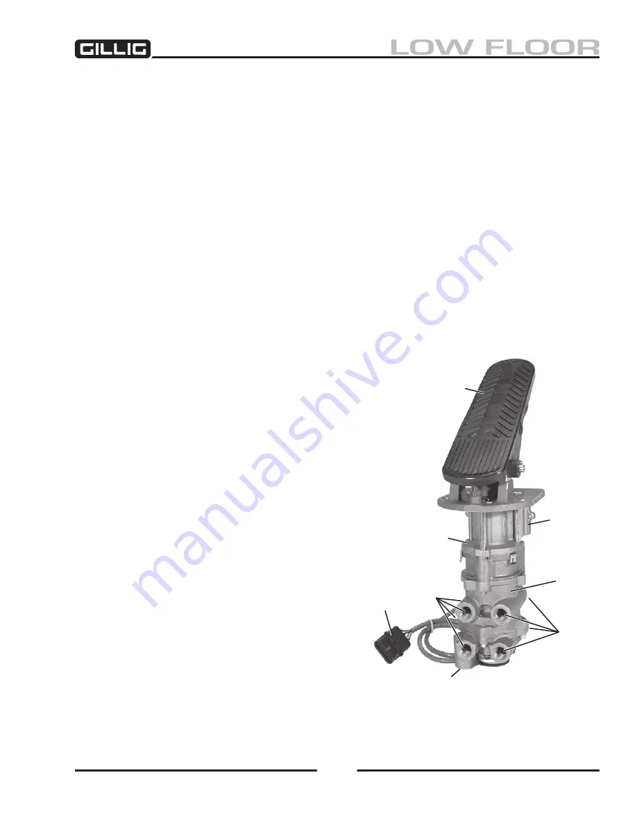
Figure 6-26, Bendix E-10R Brake Valve
Mounting
Plate
Supply
4 Ports
Electrical
Connector
Treadle
Retarder
Control
Section
Delivery
4 Ports
Valve
Auxiliary
Содержание LOW FLOOR
Страница 18: ...Specifications 18...
Страница 58: ...Preventive Maintenance 58...
Страница 110: ...Engine 110...
Страница 138: ...Transmission Driveline Rear Axle 138...
Страница 182: ...Suspension 182...
Страница 260: ...Air System 260...
Страница 420: ...Electrical System 420 Deutsch DT Series Connectors...
Страница 421: ...Electrical System 421...
Страница 422: ...Electrical System 422 Deutsch HD 10 Series Connectors...
Страница 423: ...Electrical System 423...
Страница 424: ...Electrical System 424 Deutsch HD 30 Series Connectors...
Страница 425: ...Electrical System 425...
Страница 442: ...Heating Air Conditioning 442...
Страница 486: ...Body and Interior 486 Driver s Seat Troubleshooting Use the following chart to troubleshoot the USSC seat...
Страница 492: ...Body and Interior 492 Figure 11 33 USSC Seat Assembly...
Страница 493: ...Body and Interior 493 Figure 11 34 USSC Seat Suspension Assembly...
Страница 495: ...Body and Interior 495 Figure 11 37 Seat Air Connections...
Страница 506: ...GILLIG CORPORATION 25800 Clawiter Road Hayward CA 94545 Phone 510 785 1500 Fax 510 785 6819 Printed November 2006...


