


69
Suspension
Caster
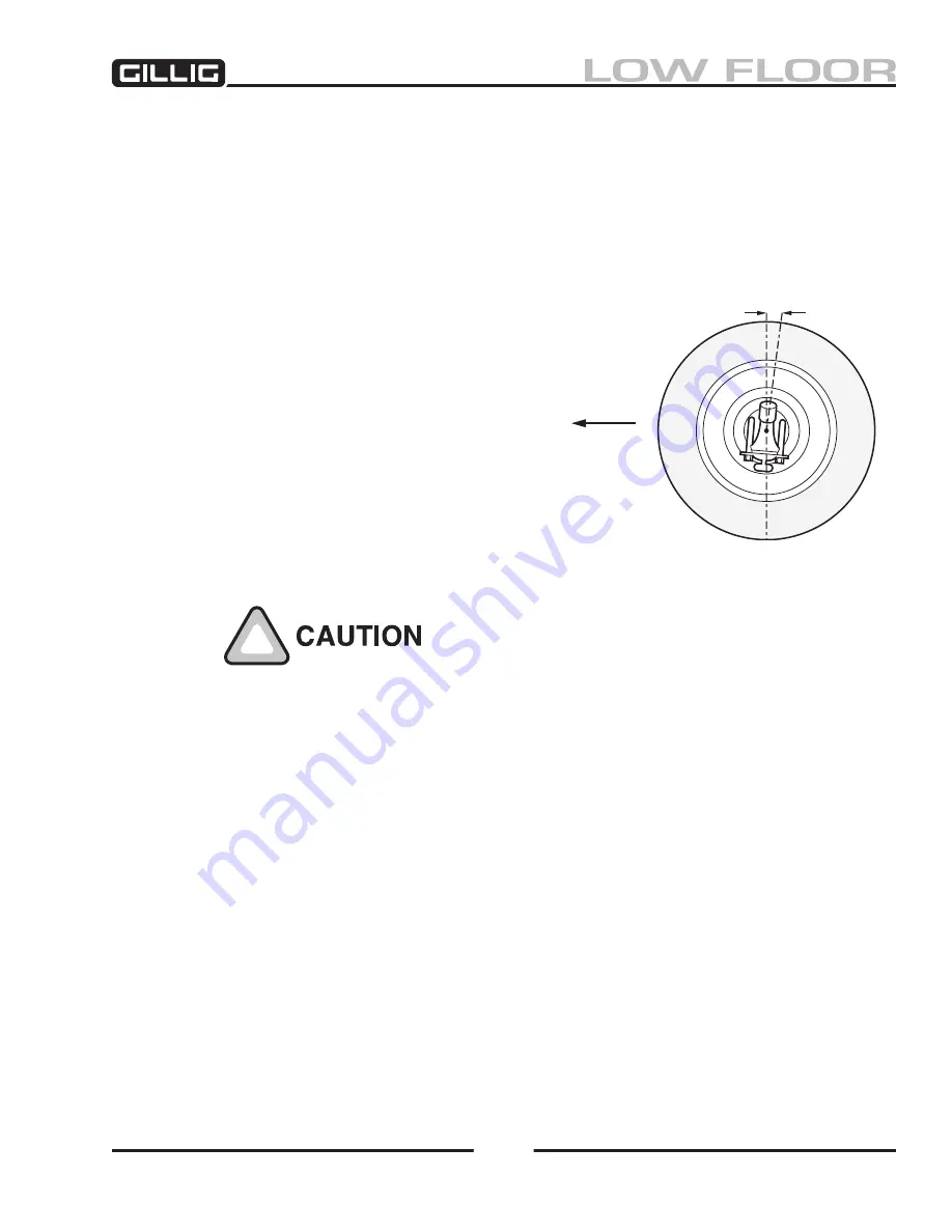
Caster is the inclination of the kingpins toward the front or rear of the vehicle (see Figure 5-9). Caster is
described as “negative” when the kingpin is angled with its top closer than the bottom to the front of the
vehicle. A vehicle is said to have “positive” caster when the kingpin is angled with its bottom closer than
the top to the front of the vehicle.
The coach axle beams have a +3 degree caster angle machined into
the beam.
Caster variations may be caused by a bent axle, worn
torque rod end bushings, or sagging of torque rod tower
assemblies. Precision gauges must be used to determine
caster when the axle is on the coach.
Caster is adjusted by changing the length of the torque
rods. Loosen the upper rod end clamps and rotate the tube,
using a pipe wrench if necessary, to set the caster to 3
degrees. When the correct setting is obtained, tighten the
clamp nuts to the specified torque. When tightening the
clamp nuts you must:
1. Tighten the torque rod clamps at the nut end only.
2. Install the clamp within 1/4" from the end of the
torque rod tube.
3. Place the mouth of the clamp over a slot in the rod.
Always adjust the torque rods as a pair, either upper or lower, and in
the
same amount for each torque rod
. If you are unable to adjust both
sides equally to 3 degrees, the axle is bent, torque rod end bushings are
worn, or rod tower assemblies are sagging.
Caster adjustment should be made using the upper pair of torque rods. If sufficient travel is not avail
-
able in the upper pair, the lower pair and upper pair must be adjusted together to obtain the specified
caster setting. The lower pair of torque rods are adjusted by loosening the two bolts in the center clamp,
spreading the clamp with a chisel, and turning the clamp itself to obtain adjustment to the length of the
torque rod. When the correct setting is reached, tighten the clamp nuts to the specified torque.
When the axle is removed from the coach, the caster can be checked on a bench. Place two uniform
blocks on a level surface. Turn the axle upside down and rest the suspension support pads on the blocks.
Use a shop protractor to determine the caster angle. If this angle is ± .5 degrees off from 3 degrees, the
axle beam is twisted and must be replaced.
Figure 5-9, Caster
A
Positive Caster
Forward
Содержание LOW FLOOR
Страница 18: ...Specifications 18...
Страница 58: ...Preventive Maintenance 58...
Страница 110: ...Engine 110...
Страница 138: ...Transmission Driveline Rear Axle 138...
Страница 182: ...Suspension 182...
Страница 260: ...Air System 260...
Страница 420: ...Electrical System 420 Deutsch DT Series Connectors...
Страница 421: ...Electrical System 421...
Страница 422: ...Electrical System 422 Deutsch HD 10 Series Connectors...
Страница 423: ...Electrical System 423...
Страница 424: ...Electrical System 424 Deutsch HD 30 Series Connectors...
Страница 425: ...Electrical System 425...
Страница 442: ...Heating Air Conditioning 442...
Страница 486: ...Body and Interior 486 Driver s Seat Troubleshooting Use the following chart to troubleshoot the USSC seat...
Страница 492: ...Body and Interior 492 Figure 11 33 USSC Seat Assembly...
Страница 493: ...Body and Interior 493 Figure 11 34 USSC Seat Suspension Assembly...
Страница 495: ...Body and Interior 495 Figure 11 37 Seat Air Connections...
Страница 506: ...GILLIG CORPORATION 25800 Clawiter Road Hayward CA 94545 Phone 510 785 1500 Fax 510 785 6819 Printed November 2006...


