240
Air System
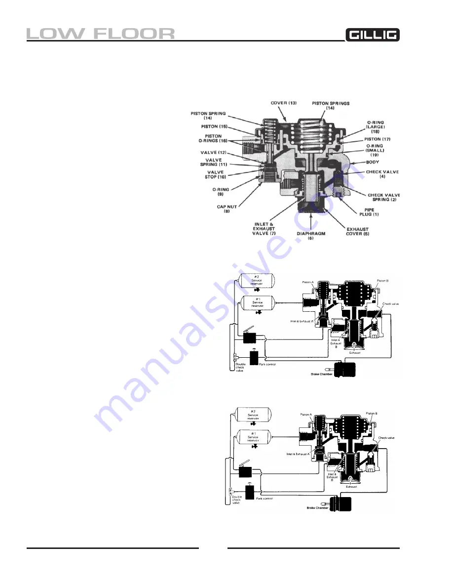
Figure 6-37, SR-1 Spring Brake Valve
Figure 6-38, Charging- Below 55 psi
Figure 6-39, System Fully Charged
Spring Brake Valve (Bendix SR-)
The SR-1 (see Figure 6-
37) supplies a hold-off pressure to the spring brakes and, in the event of air pres-
sure loss in the primary air brake system, modulates the spring brakes.
SR- Valve Operation
initial Air system charge
Upon initial charge, air from the primary
and secondary air tanks flows through the
parking brake control valve and enters the
SR-1 supply port. Air entering this port
flows past inlet/exhaust valve B to the un
-
derside of piston B and out the delivery port
of the SR-1 to the emergency air connection
at the spring brake actuator. Note that the
springs above piston B force it into contact
with inlet and exhaust valve B. In the posi-
tion shown (see Figure 6-38) the exhaust is
closed and the inlet is open.
Air flowing from the primary air tank only
enters the reservoir port of the SR-1. This air remains
under piston A as system air pressure builds. With
primary tank pressure below about 55 psi, the spring
above piston A forces it into contact with inlet/exhaust
valve A, causing the exhaust to seal and the inlet to
open.
With air system pressure above approximately 55 psi
in the primary and secondary air tanks, piston A has
moved against the force of the spring above it, allow-
ing the inlet of valve A to close and opening the hol-
low exhaust passage through piston A.
Air brake system fully charged
See Figure 6-
39. When air pressure beneath piston
B is about 80 psi, piston B rises slightly, against the
force of the springs above it, allowing the inlet of
valve B to close. The exhaust of valve B remains
closed. The closing of the inlet portion of valve B
retains about 100 psi in the hold-off cavity of the
spring brake actuators while allowing full air system
pressure to build elsewhere in the system.
brake Application- Air tanks fully charged
Refer to Figure 6-
40
. When a service application
Содержание LOW FLOOR
Страница 18: ...Specifications 18...
Страница 58: ...Preventive Maintenance 58...
Страница 110: ...Engine 110...
Страница 138: ...Transmission Driveline Rear Axle 138...
Страница 182: ...Suspension 182...
Страница 260: ...Air System 260...
Страница 420: ...Electrical System 420 Deutsch DT Series Connectors...
Страница 421: ...Electrical System 421...
Страница 422: ...Electrical System 422 Deutsch HD 10 Series Connectors...
Страница 423: ...Electrical System 423...
Страница 424: ...Electrical System 424 Deutsch HD 30 Series Connectors...
Страница 425: ...Electrical System 425...
Страница 442: ...Heating Air Conditioning 442...
Страница 486: ...Body and Interior 486 Driver s Seat Troubleshooting Use the following chart to troubleshoot the USSC seat...
Страница 492: ...Body and Interior 492 Figure 11 33 USSC Seat Assembly...
Страница 493: ...Body and Interior 493 Figure 11 34 USSC Seat Suspension Assembly...
Страница 495: ...Body and Interior 495 Figure 11 37 Seat Air Connections...
Страница 506: ...GILLIG CORPORATION 25800 Clawiter Road Hayward CA 94545 Phone 510 785 1500 Fax 510 785 6819 Printed November 2006...


