Engine
09
ENGINE DIAGNOSTICS
The Cummins Engine Control System will display and record engine faults, which will be shown as
fault codes. The fault codes are recorded in the ECM and can be read at the CHECK ENGINE and
STOP ENGINE lamps on the drivers indicator lamp strip. The following is a brief description. Refer to
the Cummins
Troubleshooting and Repair Manual
for fault codes and more details. More complete di-
agnostic information may be obtained by interfacing with the ECM via a laptop computer and software
available from Cummins.
To check for active engine electronic system fault codes:
1. Turn the ignition switch to the OFF position.
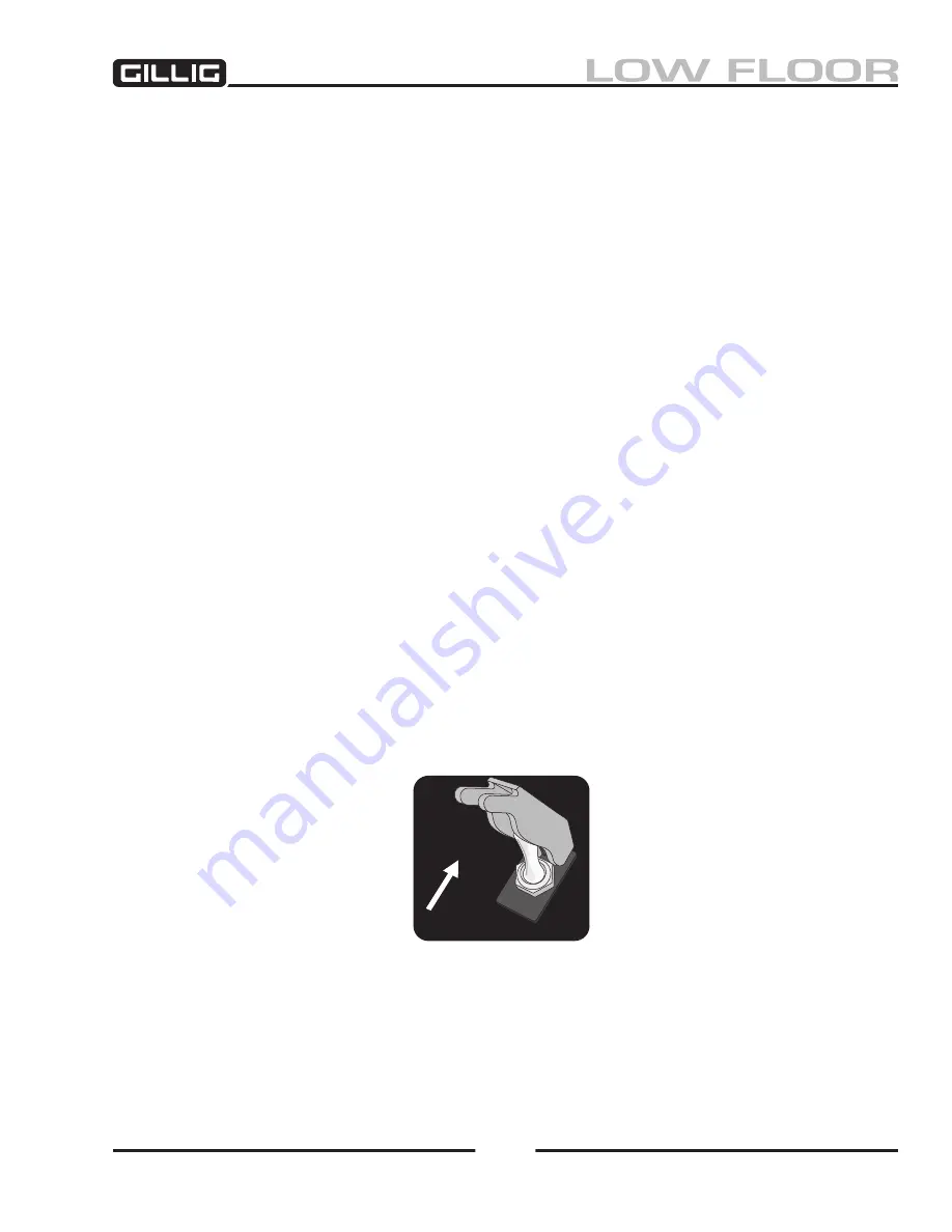
2. Move the ENGINE TEST switch to the TEST position (Figure 3-
28).
3. Turn the ignition switch to the ON position.
4. If no active fault codes are recorded, both the CHECK ENGINE and the STOP ENGINE lamps
will come on and stay on.
5. If active fault codes are recorded, both the CHECK ENGINE and the STOP ENGINE lamps will
come on momentarily, then will begin to flash the code of the recorded faults.
6. The fault code will flash in the following sequence:
a. A yellow CHECK ENGINE lamp will flash.
b. A short one or two second pause will occur.
c. The fault code will flash on the red STOP ENGINE lamp.
d. A short one or two second pause will occur between each number.
e. When the number has finished flashing on the STOP ENGINE lamp, a yellow CHECK EN
-
GINE lamp will appear again. The three digit code will repeat in the same sequence.
When not using the fault codes, turn off the ENGINE TEST switch. If the switch is left on, the ECM
will not log some fault codes.
ENGINE
TEST
30-100-211
Figure 3-28, Engine Test Switch
Содержание LOW FLOOR
Страница 18: ...Specifications 18...
Страница 58: ...Preventive Maintenance 58...
Страница 110: ...Engine 110...
Страница 138: ...Transmission Driveline Rear Axle 138...
Страница 182: ...Suspension 182...
Страница 260: ...Air System 260...
Страница 420: ...Electrical System 420 Deutsch DT Series Connectors...
Страница 421: ...Electrical System 421...
Страница 422: ...Electrical System 422 Deutsch HD 10 Series Connectors...
Страница 423: ...Electrical System 423...
Страница 424: ...Electrical System 424 Deutsch HD 30 Series Connectors...
Страница 425: ...Electrical System 425...
Страница 442: ...Heating Air Conditioning 442...
Страница 486: ...Body and Interior 486 Driver s Seat Troubleshooting Use the following chart to troubleshoot the USSC seat...
Страница 492: ...Body and Interior 492 Figure 11 33 USSC Seat Assembly...
Страница 493: ...Body and Interior 493 Figure 11 34 USSC Seat Suspension Assembly...
Страница 495: ...Body and Interior 495 Figure 11 37 Seat Air Connections...
Страница 506: ...GILLIG CORPORATION 25800 Clawiter Road Hayward CA 94545 Phone 510 785 1500 Fax 510 785 6819 Printed November 2006...


