Non-Overhaul Removal and Replacement
Teledyne Continental Motors, Inc.
TM
10-40
IOF-550 Permold Series Engine Maintenance Manual
1 April 2007
ECU
Ground
Points
ECU
Ground
Points
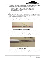
Figure 10-36.
Grounding Points for the ECU
CAUTION: Each ECU requires two independent ground straps
mounted to the airframe with at least four inches separation
between airframe mounting points. Choose airframe grounding
points that will allow the shortest possible strap length.
3.
Install the ECU in the location designated in the aircraft maintenance manual with
four bolts.
4.
Bond the ECU to the airframe with two ground straps (see Figure 10-36) per ECU
according to instructions in Section 10-6.3, “Ground Strap Installation.”
5.
Route the ECU end of the ignition lead wires to the appropriate ECU. Each ignition
lead wire has a metal identification (ID) tag that designates the cylinder and spark
plug assignment. For example, 2T designates the lead is for Cylinder 2 top spark plug
and 2B is for Cylinder 2 bottom spark plug.
6.
Spray a small amount of MS 122 DF Spray in each ECU spark tower.
7.
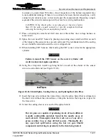
Connect each high voltage harness lead wire to the appropriate ECU spark tower.
Each spark tower is identified with a two-digit code of the same format as the ignition
lead wire ID tags (Figure 10-37).
Spark Tower Identification
Spark Tower Identification
Figure 10-37.
Ignition Lead Wire Connections to ECUs
8.
Install the 50-pin connector according to Section 10-6.1, “ECU or SSA Connector
Installation.”


