Non-Overhaul Removal and Replacement
Teledyne Continental Motors, Inc.
TM
10-96
IOF-550 Permold Series Engine Maintenance Manual
1 April 2007
9.
Position the pushrod housings into respective ports on the crankcase.
10.
While the spring is compressed and the housing is installed in the crankcase, slide a
new O-ring seal on the
cylinder
end of the pushrod housing.
11.
Insert the pushrod housing into the crankcase guide until the other end can be aligned
with the cylinder head opening.
12.
Move the assembly outward until the gasket has entered cylinder hole.
13.
Release the spring slowly until it is free. Verify the oil ring seal is in place.
14.
Remove the Pushrod Spring Compressor Tool.
15.
Install the pushrods, rocker arms, and rocker covers according to instruction in
Section 10-8.13 or
16.
Install any airframe equipment, accessories, and cowling removed to facilitate
hydraulic tappet replacement according to the airframe manufacturer’s instructions.
17.
Perform an “Engine Operational Check” according to instructions in Chapter 6.
10-8.13. IOF-550-B & C Valve Mechanism and Pushrod Installation
Procedure
1.
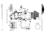
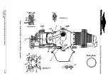
With the engine upright, lubricate the pushrods (39) (Figure 10-59) with clean 50-
weight aviation engine oil and install the pushrods through the cylinder openings into
the pushrod housings (35).
2.
Before installing the valve actuating parts on each cylinder, turn the crankshaft until
the pushrods are at their lowest position in the cylinder.
3.
Position the crankshaft so the piston is at top dead center and both the intake and
exhaust lobes on the camshaft for the cylinder being installed are facing away from
the cylinder.
4.
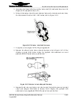
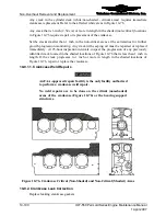
Slide the valve rocker shafts (18) out far enough to install the rocker arms (21 & 24)
and thrust washers (27). Verify clearance of 0.020 inches between the rocker arm and
rotocoil. Refer to Figure 10-71. The underside of the rocker arm may be smoothly
ground to attain the specified 0.020-inch minimum clearance as instructed in
“Machining the Rocker-Arm-to-Rotocoil Clearance” in Chapter 9 of the TCM
Overhaul Manual (OH-24).
Figure 10-71.
Rocker Arm to Rotocoil Clearance
R
P
N
C
B


