Teledyne Continental Motors, Inc.
TM
Troubleshooting
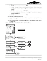
Fuel
Injection Operational
Check, cont.
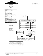
Set SSA Simulator Switches:
Engine ……………………..TCM
Cylinders ……………………....6
Speed………………....Midrange
Power………………………..ON
Purge fuel lines for one minute.
Power……………..………..OFF
Empty catch cans and return catch cans to the
tubing ends.
Power……………………….ON
Collect fuel for one minute
Power………………………OFF
Ignition Switch…………….OFF
Pour contents of each catch can contents in to a
burette or other precisely graduated container.
Record the volume of each catch can for
comparison. Variation between injectors should not
exceed 3%. Discard fuel waste.
Replace faulty injector
(Sect. 10-6). Repeat Fuel
Injector Operational Check.
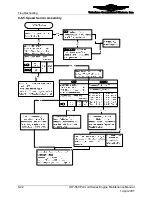
Disconnect P1, P2 and P3 from the ECUs. Measure resistance at 50-
pin connector pins listed. Resistance should be 2.3-2.6 ohms for 12V
electrical systems and 5.6-5.9 ohms for 24V electrical systems.
N P R
Injector
B C
P1 pins 3 and 4
CYL 1
P1 pins 3 and 4
P1 pins 5 and 6
CYL 2
P1 pins 5 and 6
P2 pins 3 and 4
CYL 3
P2 pins 3 and 4
P2 pins 5 and 6
CYL 4
P2 pins 5 and 6
P3 pins 3 and 4
CYL 5
P3 pins 3 and 4
P3 pins 5 and 6
CYL 6
P3 pins 5 and 6
Replace ECU
(Sect. 10-6).
Flow normal-deviation
between catch cans
less than 3%
Catch can empty
or volume deviation
between cans
exceeds 3%
Solenoid or wiring fault. Repair
wire or replace solenoid (Sect.
10-5). Repeat Fuel Injector
Operational Check.
OK
NOT
OK
Install the 50-pin connectors (Sect. 10-6)
Secure the engine low voltage harness (App. C)
Perform a FADEC Level I Diagnostics ( Sect. 8-6.1)
Perform Engine Operational Check (Sect. 6-1)
Remove the SSA simulator from the
25-pin connectors.
Connect the 25-pin connectors to
the Signal Conditioner (Sect. 10-6).
B
C
Disconnect the SSA Simulator from
the 13 pin connectors.
Install the 13-pin connectors from
the oil sump (Sect. 10-6).
N
P
R
OK
OK
IOF-550 Permold Series Engine Maintenance Manual
8-11
1 April 2007


