Teledyne Continental Motors, Inc.
TM
Maintenance
Inspections
IOF-550 Permold Series Engine Maintenance Manual
7-29
1 April 2007
7-3.8.4. Cylinder-to-Crankcase Mounting Deck Inspection
Purpose
Proper cylinder head torque requires a solid mounting surface. Foreign materials, such as
grease or unauthorized sealants applied to the mounting base or flange distort the desired
mating surface and alter torque readings. Proper torque is critical to engine operation.
Frequency
During 100 hour or annual inspection
WARNING
The use of silicone RTV sealant or other sealant applied
between the cylinder base flange and the crankcase mounting
deck will cause a loss of torque and can severely damage the
crankcase, possibly resulting in separation of the cylinder from
the crankcase causing sudden loss of engine oil and subsequent
engine failure.
Procedure
Inspect the cylinder-to-crankcase mounting deck for evidence of silicone RTV sealant on
the cylinder deck flange. If silicone RTV sealant is discovered:
1.
Remove the cylinder according to “Cylinder Removal” instructions in Chapter 10,
“Non-Overhaul Repair and Replacement.”
2.
Check the cylinder for serviceability.
3.
Thoroughly clean the cylinder base flange and crankcase mounting deck.
4.
Replace the cylinder base packing.
5.
Reinstall the cylinder as described in Chapter 10, “Non-Overhaul Repair and
Replacement.”
6.
Perform the “Cylinder Torque Procedure” in Appendix B.
7-3.8.5. Baffle Inspection
Purpose
To prevent premature cylinder deterioration and verify baffles are properly fitted and
installed. This inspection performed in concert with the cylinder inspection.
The heat transfer in piston engines requires efficient and reliable operation of cooling
baffles to prevent rapid deterioration of the cylinders and other engine components.
Verify the baffles are installed, intact, and positioned properly.
Frequency
•
During 100-hour or annual inspections.
Procedure
Check the following for deterioration, wear, correct position, and proper contact wit
1.
h
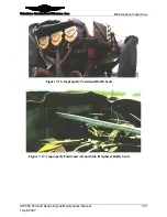
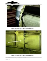
ugh Figure 7-18 show improperly positioned baffle seals.
les
the cowl. Figure 7-15 thro
a.
Inter-cylinder baff


