Teledyne Continental Motors, Inc.
TM
Non-Overhaul Removal and Replacement
IOF-550 Permold Series Engine Maintenance Manual
10-57
1 April 2007
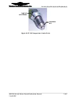
CAUTION: Failure to install the CHT sensors on the correct
cylinder will result in abnormal engine operation.
5.
For proper engine operation, route, clamp, support, and protect the engine low voltage
harness wires to prevent chafing, fretting, and wear of the lead wires. Route and
secure the harness according to Appendix C, “Harness Routing.”
6.
Perform a “FADEC Level I Diagnostics” in Chapter 8, Troubleshooting of this
manual to check the FADEC System. If the FADEC System fails this diagnostic
check, troubleshoot the system until the malfunction is corrected.
7.
Perform an “Engine Operational Check” according to the instructions in Chapter 6,
Operational Performance Checks.
10-6.23. Two Lamp HSA Removal
Procedure
1.
The two lamp HSA driver is mounted in the airframe according to airframe
manufacturer’s instructions. Consult the manufacturer’s documentation for location
and removal instructions.
2.
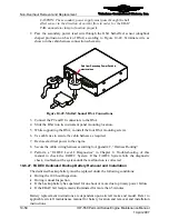
Remove the connector secured by two screws.
10-6.24. Two Lamp HSA Installation
Procedure
1.
Install the connector on HSA driver and secure with two screws.
2.
Install the lamp driver according to aircraft maintenance manual instructions.
3.
Perform a “FADEC Level I Diagnostics” in Chapter 8, Troubleshooting of this
manual to verify lamp operation.
10-6.25. HSA with Battery Condition Monitor Removal
Procedure
1.
Disconnect electrical power to the engine.
2.
Remove instrument panel components as necessary to gain access to the rear of the
HSA per the aircraft maintenance manual.
3.
With the HSA properly supported, remove the HSA mounting screws. Then re-install
two of these screws after the HSA is removed from its mounting to retain the
faceplate on the HSA.
4.
Slide the HSA out of the instrument panel.
5.
Disconnect the P9 and J10 connectors from the HSA.
6.
Disconnect one end of the conductor passing through the hall-effect sensor (doughnut
shaped protrusion on back of HSA) and remove from the sensor.
7.
Remove the HSA from the aircraft.
10-6.26. HSA with Battery Condition Monitor Installation
Procedure
1.
Disconnect engine electrical power.


