Non-Overhaul Removal and Replacement
Teledyne Continental Motors, Inc.
TM
10-46
IOF-550 Permold Series Engine Maintenance Manual
1 April 2007
WARNING
Make sure all personnel are standing clear of the propeller’s
path of rotation to avoid injury.
5.
Note the position of the propeller. Rotate the propeller in the normal running direction
(CW as viewed from cockpit) through two complete revolutions while observing the
Test Indicator LEDs. Notice the indicators switching ON and OFF as the holes in the
camshaft intersect the sensors.
NOTE: Channel 2 (N
c2 /
N
e2
) and Channel 3 (N
c3 /
N
e3
) LEDs will
illuminated approximately 5 degrees after Channel 1 (N
c1 /
N
e1
).
6.
Use a TDC locator to find TDC on Cyl #1. Observe the FADEC Timing Tool LEDs;
the N
c1
LEDs should “blink” at approximately 11° BTDC.
7.
Slowly rotate the propeller clockwise while observing the tester LEDs.
a.
The N
c1
LEDs will blink once in two propeller revolutions just before TDC.
b.
In two propeller revolutions, the N
e1
LEDs will blink 11 times.
8.
If the newly installed SSA fails the operational check, troubleshoot the speed sensor
assembly according to “Speed Sensor Assembly Troubleshooting” in Chapter 8,
Troubleshooting.
9.
If the SSA passes the operational check, disconnect the FADEC Timing Tool and
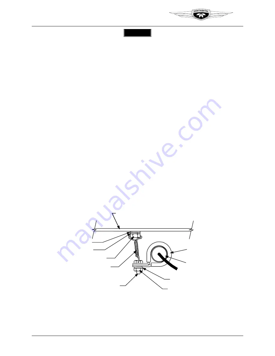
connect the 13-pin connectors at the sump. Install a clamp with a bolt, washer, and
self-locking nut as illustrated in Figure 10-41. Torque the nuts to Appendix B
specifications and safety wire the bolt to the adjacent oil sump bolt according to
Appendix C safety wire instructions.
OIL SUMP RAIL
CONNECTOR
CLAMP
WASHER
SELF LOCKING NUT
BOLT
LOCKWIRE
SUMP BOLT
LOCKWASHER
WASHER
Figure 10-41.
SSA Connector Safety Wire
10.
Clean, gap and install the spark plugs with new copper gaskets. Refer to “Ignition
System Maintenance” in Chapter 9 of this manual for spark plug installation and high
voltage harness connection instructions. Torque the spark plug and high voltage
harness according to Appendix B specifications.


